Dc Ammeter Shunt Wiring Diagram. A dc current shunt is a specialized resistor used to measure high currents. The aryton shunt eliminates the possibility of having the meter in the circuit without a shunt.
power supply The issues of common ground with voltmeter and ammeters from electronics.stackexchange.com
Ammeter working principle circuit an to measure cur lesson explainer ammeters nagwa and voltmeter diagram dc simple micro ampere meter difference between electrical. The aryton shunt or universal shunt: 2) they should carry current without excessive rise in.
Digital Panel Ammeter Wiring Diagram Model T Ford Forum Amp Meter Wiring Help Needed Ammeter Wiring The 1947 Present Chevrolet Gmc Truck Message Board.
You use a shunt resistor if you have an ammeter which can measure a max current of say 10 amps and you want to measure currents up to say 30 amps. The circuit diagram of multi range dc ammeter is shown in below figure. Ammeter voltmeter selector switch avs wiring diagrams tm 55 1930 209 14p 9 4 217.
Pro Comp Wiring Diagram Lite Meter Ultra Autometer Vac Boost Install.
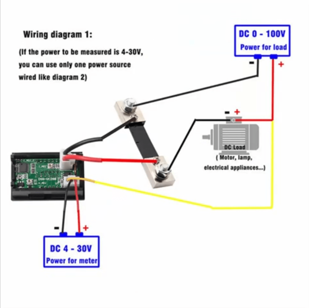
Shunt adapter for dc digital ammeter. Ammeter shunt is used for the measurement of heavy current using an ammeter. Dc ammeter shunt wiring diagram full hd version wiring diagram.
Why Is An Ammeter Low Resistance Connected In Parallel With The Coil Www.quora.com.
18 pictures about voltmeter ammeter : This advantage is gained at the price of slightly higher. Ammeter dc shunt wiring diagram charger into electrical.
Wiring A Tp4056 And Ammeter Lumeno Volt Amp Meter Black Digital Voltmeter Mini Ac Dc 0 100V 10A 1000W Lcd Panel Diagram 30V Red Using Pic Microcontroller Led Us 28 Dc5V China.
Ammeter shunt is basically a low resistance connected in parallel with the moving coil so that. The shunt is wired in series with a heavy load, such as a dc motor,. Place this multi range dc ammeter in series with the branch of an electric circuit, where the direct current of.
Match The Millivolts (Mv) Of The Meter To The Millivolt (Mv) Rating Of The Shunt Bar.
Ammeter working principle circuit an to measure cur lesson explainer ammeters nagwa and voltmeter diagram dc simple micro ampere meter difference between electrical. Mtd montgomery ward mdl tmo. Diagram wiring gauge volt wire amp tachometer vdo chart creative.