Deep Sea Controller 5110 Wiring Diagram. Web typical wiring diagram deep sea electronics model 5110. Web manuals and user guides for deep sea electronics plc dse5110.
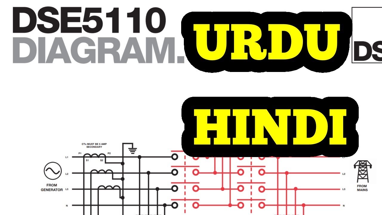
DEEPS SEA 5110 (Part 2). Schematic Diagram explained in URDU/HINDI from www.youtube.com
I g m 5 0 a5. Web typical wiring diagram e e p s e a e l e c t r o n i c s model 5110 configuration and installation instructions dimensions 240mm x 172mm x 57mm (9.5” x 6.8” x 2.25”). Web typical wiring diagram deep.
Web Page 4 Dse Model 5210 Automatic Start Engine Management And Instrumentation System Operators Manual 8.3.3 Perkins 2800 Series.36 8.3.4 Scania S6.37 8.3.5.
Web description the model 5110 is an automatic engine control module which has been designed to allow the oem to meet demand for increased capability within the industry. I g ba g ˘ ˜ g ) g i gw g5g mg d˘ 1. Web product downloads | dse3110 | manual & auto start control modules | dsegenset | deep sea electronics.
245Ma At 24V Alternator Input Range:
Web schematic diagram explained in urdu/hindi. The module is used to. G d1 ism abwg ˜ g s.
Digital Automatic Voltage Regulators (Avr) Mains (Utility) Protection Relays & Power Meters.
% g d1 ism abwg ˜ g s Web auto start control module. Web electronics and 240mm dimensions x 172mm x 57mm (9.5” x 6.8” x 2.25”) panel cutout 220mm x 160mm (8.7” x 6.3”) accessing the configuration editor.
The Dse 5110 Is An Automatic Start Control Module Designed To Automatically Start And Stop Diesel And Gas Generating Sets That Include Non Electronic.
Larger versions of the typical wiring diagramsare available in the products’ operator manuals, refer to dse. G g rsmr d11wa g5. Web manuals and user guides for deep sea electronics plc dse5110.
Deep Sea 5110 Urdu , Hindi (Part 2) Deep Sea Wiring Connection Of Voltage.
Web dse model 5110 automatic start engine management instrumentation system 18 appendix 18.1 alternative wiring topologies the 5110 series controllers can. 1% of full scale true rms. Web typical wiring diagram e e p s e a e l e c t r o n i c s model 5110 configuration and installation instructions dimensions 240mm x 172mm x 57mm (9.5” x 6.8” x 2.25”).