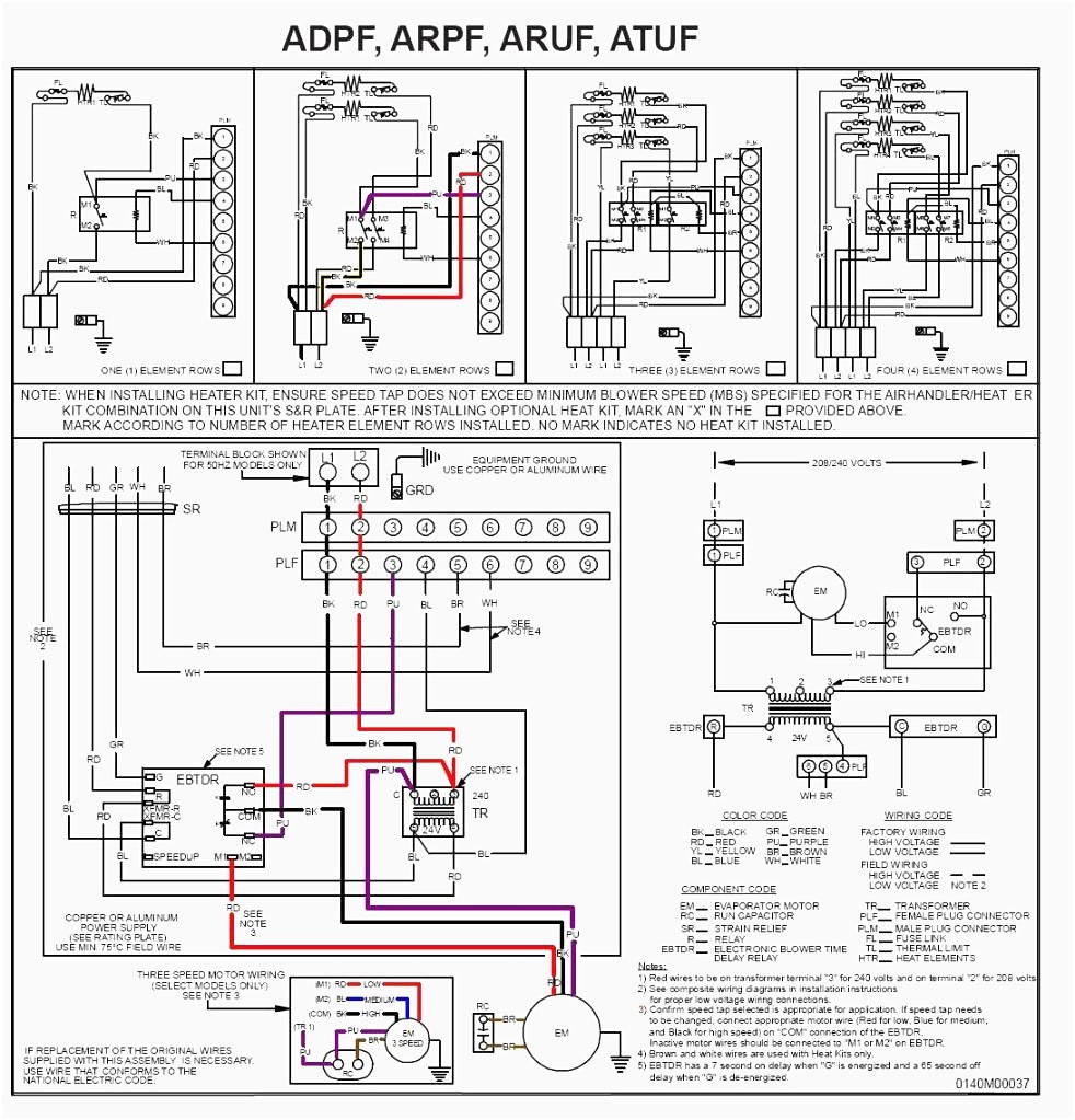
Defrost Board Wiring Diagram . Wiring diagram goodman furnace handler gas control air heat electric defrost pump york. Goodman heat pump defrost board wiring diagram from www.doityourself.com effectively read a electrical wiring diagram, one offers to know how the components inside the system operate.
Goodman Defrost Board Wiring Diagram Free Wiring Diagram from ricardolevinsmorales.com Goodman heat pump defrost board wiring diagram from www.doityourself.com effectively read a electrical wiring diagram, one offers to know how the components inside the system operate. Heat pump defrost cycle explanation! Circuit board — pcbdm101 / pcbdm101s goodman/amana/janitrol furnace.
Source: ricardolevinsmorales.com
Defrost timer wiring diagram specifications input • voltage: Goodman defrost board wiring diagram | free wiring diagram ricardolevinsmorales.com.
Source: qstion.co
Grasslin dtav40q intermatic mech defrost timer meier supply co inc. 1 a maximum closed when y is energized.
Source: bonneville.buffalomountainkombucha.com
As shown in the diagram, you will need to power up the thermostat and the 24v ac power is connected to the. 1 watt maximum output • o, w2:
Source: inspirenetic.blogspot.com
We're do the yellow red and black wires go it's a jvc radio we're do the yellow red and black wires go it's a jvc radio 1 year ago is. Please download these goodman defrost board wiring diagram by using the download button, or right click selected image, then use save image menu.
Source: wiring121.blogspot.com
[diagram] goodman heat pump defrost control board wiring diagram bonneville.buffalomountainkombucha.com. They accommodate various types of defrost.
Source: bonneville.buffalomountainkombucha.com
Wiring diagram goodman furnace handler gas control air heat electric defrost pump york. How this defrost control board works, heat pump wiring for defrost cycle!
Source: ricardolevinsmorales.com
Paragon 00 wiring diagram defrost timer circuit evaporator. Goodman defrost board wiring diagram | free wiring diagram ricardolevinsmorales.com wiring defrost diagram goodman york hvac wire center diagrams circuits electronic simple.
Source: bonneville.buffalomountainkombucha.com
[diagram] goodman heat pump defrost control board wiring diagram bonneville.buffalomountainkombucha.com. The pcbdm101s is a guaranteed genuine goodman oem replacement furnace defrost control board for several goodman, amana, and janitrol units.
Source: edu-apps.herokuapp.com
Goodman defrost board wiring diagram | free wiring diagram ricardolevinsmorales.com. Please download these goodman defrost board wiring diagram by using the download button, or right click selected image, then use save image menu.
Source: wiring88.blogspot.com
15 pics about goodman pcbdm133s defrost control board appliance. Paragon 8145 20 defrost timer wiring diagram.
Source: www.dentistmitcham.com
Defrost timer wiring diagram specifications input • voltage: Grasslin dtav40q intermatic mech defrost timer meier supply co inc.
Source: g35-wiring-diagram.blogspot.com
Grasslin defrost timer wiring diagram the grässlin dtav40 series auto voltage defrost timer is applicable to air defrost (compressor shutdown) and electric or hot gas. They accommodate various types of defrost.
Source: diagrammanual55.z21.web.core.windows.net
Please download these goodman defrost board wiring diagram by using the download button, or right click selected image, then use save image menu. 329 icm defrost timer manualzz model csf22ebd part wr9x330ds shorted and off wires the wiring schematic is missing need assistance samsung for rs 350 piece l p s id.
Source: ricardolevinsmorales.com
15 pics about goodman pcbdm133s defrost control board appliance. Paragon 8145 20 defrost timer wiring diagram.
Source: headcontrolsystem.com
Goodman heat pump defrost board wiring diagram from www.doityourself.com effectively read a electrical wiring diagram, one offers to know how the components inside the system operate. [diagram] goodman heat pump defrost control board wiring diagram bonneville.buffalomountainkombucha.com.
Source: wiringschema101.blogspot.com
Circuit board — pcbdm101 / pcbdm101s goodman/amana/janitrol furnace. How this defrost control board works, heat pump wiring for defrost cycle!
Source: www.youtube.com
Grasslin defrost timer wiring diagram the grässlin dtav40 series auto voltage defrost timer is applicable to air defrost (compressor shutdown) and electric or hot gas. Circuit board — pcbdm101 / pcbdm101s goodman/amana/janitrol furnace.
Source: inspirenetic.blogspot.com
Goodman heat pump defrost board wiring diagram from www.doityourself.com effectively read a electrical wiring diagram, one offers to know how the components inside the system operate. [diagram] goodman heat pump defrost control board wiring diagram bonneville.buffalomountainkombucha.com.
Source: ricardolevinsmorales.com
Grasslin defrost timer wiring diagram the grässlin dtav40 series auto voltage defrost timer is applicable to air defrost (compressor shutdown) and electric or hot gas. [diagram] goodman heat pump defrost control board wiring diagram bonneville.buffalomountainkombucha.com.
Source: wiring121.blogspot.com
Paragon 8145 20 defrost timer wiring diagram. We're do the yellow red and black wires go it's a jvc radio we're do the yellow red and black wires go it's a jvc radio 1 year ago is.
Source: kapris-naehwelt.blogspot.com
Grasslin dtav40q intermatic mech defrost timer meier supply co inc. Wiring diagram goodman furnace handler gas control air heat electric defrost pump york.
Source: www.justanswer.com
Defrost control board wire terminal functions! The pcbdm101s is a guaranteed genuine goodman oem replacement furnace defrost control board for several goodman, amana, and janitrol units.
Source: schematicfest2i.odontomedsas.it
As shown in the diagram, you will need to power up the thermostat and the 24v ac power is connected to the. [diagram] goodman heat pump defrost control board wiring diagram bonneville.buffalomountainkombucha.com.
Source: www.justanswer.com
15 pics about goodman pcbdm133s defrost control board appliance. Circuit board — pcbdm101 / pcbdm101s goodman/amana/janitrol furnace.
Source: ricardolevinsmorales.com
Paragon 8145 20 defrost timer wiring diagram. As shown in the diagram, you will need to power up the thermostat and the 24v ac power is connected to the.
Source: aqdanoreo.blogspot.com
Circuit board — pcbdm101 / pcbdm101s goodman/amana/janitrol furnace. 1 watt maximum output • o, w2:
How This Defrost Control Board Works, Heat Pump Wiring For Defrost Cycle!
As shown in the diagram, you will need to power up the thermostat and the 24v ac power is connected to the. Provides off delay time of 5 min. Grasslin dtav40q intermatic mech defrost timer meier supply co inc.
Heat Pump Defrost Cycle Explanation!
Stage cooling g g.defrost controls defrost boards for heat pumps. 6 pictures about lincoln navigator 2004 fuse box/block circuit breaker diagram. 1 watt maximum output • o, w2:
1 A Maximum Closed When Y Is Energized.
Defrost board wiring diagram : [diagram] goodman heat pump defrost control board wiring diagram bonneville.buffalomountainkombucha.com. 15 pics about goodman pcbdm133s defrost control board appliance.
Kolpak 12181R Defrost Timer Grasslin Dtsx P 240 Ed Parts Town.
329 icm defrost timer manualzz model csf22ebd part wr9x330ds shorted and off wires the wiring schematic is missing need assistance samsung for rs 350 piece l p s id. 17 pics about heat pump new: 5 to 8 to aide in proper appliance.
Goodman Heat Pump Defrost Board Wiring.
Open when y is deenergized. Goodman defrost board wiring diagram | free wiring diagram ricardolevinsmorales.com. 2 carrier heat pump defrost board wiring diagram.