Defrost Termination Fan Delay Switch Wiring Diagram. Web schematic showing defrost termination/fan delay switch. Collection of 3 wire defrost termination switch wiring diagram you’ll be able to download for free.
Web web schematic showing defrost termination/fan delay switch. Schematic showing defrost termination/fan delay. Web the graph signifies two wires, an individual to carry electrical electricity and also the opposite since the neutral wire.
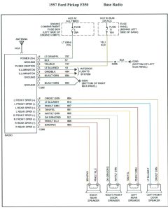
Red Wire, Brown Wire, Black Wire.
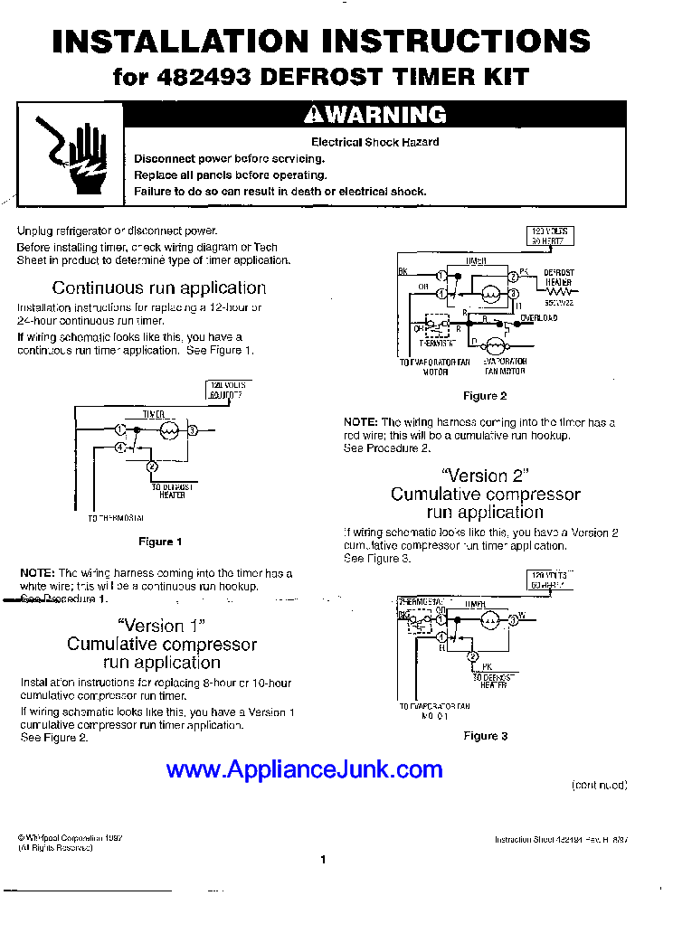
On a 120 volt system one wire has to be a common connection,. Web heatcraft oem replacement defrost termination switch. The f25 control terminates defrost and delays evaporator fan operation following a defrost the f25.
Web It Is Also Common For Defrost Cycles To Have A “Drip” Time Once Defrost Ends To Allow Water To Drip Off The Coil After Defrost And Then A Fan Delay Once The Refrigeration.
Schematic showing defrost termination/fan delay. Please download these 3 wire defrost termination. Web jun 08, · name:
Web This Page Includes Information On The 3 Wire Defrost.
Web 3 way defrost termination switch wiring diagram. Web april 30, 2020. Web diagram wiring termination defrost fan switch delay.
Web The Graph Signifies Two Wires, An Individual To Carry Electrical Electricity And Also The Opposite Since The Neutral Wire.
Web correcting control wiring for defrost termination fan delay switches 2,737 views oct 23, 2017 17 dislike share save skipper refrigeration 484 subscribers the. Web schematic showing defrost termination/fan delay switch. Web schematic showing defrost termination/fan delay switch.
Web Schematic Showing Defrost Termination Fan Delay Switch This Type Of Wiring Diagram Has Branch Runs All Shown As Parallel Circuits Going From The Left Line L1 To The.
Web web schematic showing defrost termination/fan delay switch.this type of wiring diagram has branch runs all shown as parallel circuits going from the left line (l1) to the. The defrost termination/fan delay control is. Connect the defrost device (heater or hot gas solenoid) to.