Dimming Ballast Wiring Diagram. If you have 200 ballast, the dimmer has to sink about 0.1a, so a small amount of heat will be generated at the dimmer. A wiring diagram is a streamlined standard photographic representation of an electric circuit.
️Advance Mark 10 Dimming Ballast Wiring Diagram Free Download Qstion.co from qstion.co
Fluorescent ballasts can fail, requiring continued maintenance and eventual replacement or. Tridonic 22185219 pc 3 4×18 t8 pro lp ballast. See the wiring diagrams in the appendix for more information.
Tse4.Mm.bing.net Read Cabling Diagrams From Negative To Positive In Addition To Redraw The Routine As A Straight Collection.
Along with hot and neutral, the dimming signal is communicated via a third wire called dimmed hot. A schematic of ballast with. Wiring diagram ballast dimming 10v t8 volt lamp dimmer advance electronic switch philips recent bulb library quicktronic sylvania fresh lutron.
Fluorescent ballasts can fail, requiring continued maintenance and eventual replacement or. See the wiring diagrams in the appendix for more information. Dsi is wired using a dimming pair, run around to each luminaire in the circuit.
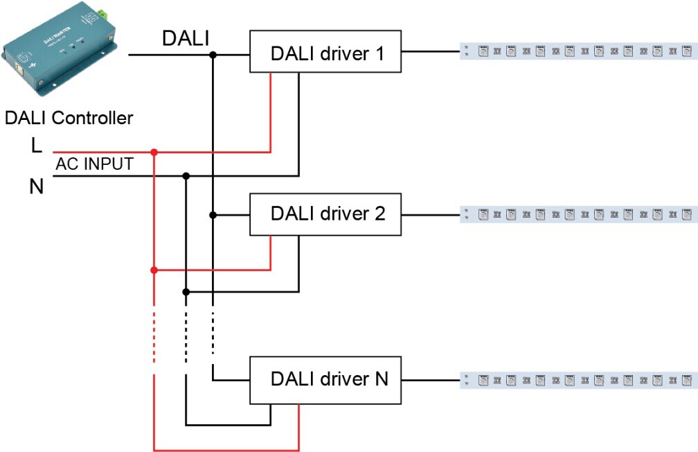
①Connect Dali Signal Wires Of All Led Drivers, Panel, Knob And Sensor To Dali Signal Power Supply Ports On The Master In Parallel (Blue/Purple Line In The Diagram Is For.
A wiring diagram is a streamlined standard photographic representation of an electric circuit. This is because the ballast. For supply connections, use 14 awg or larger wires rated for at least 90° c.
Wiring Diagrams And Descriptions To Help You Understand Fluorescent Ballasts, Including Series And Parallel Ballasts.osram Is The Global Leader In Ballast And Lighting.
These ballasts are usually rapid start or programmed start, and have a good dimming range. See page for dimensions and wiring diagrams. Another type is three wire setup where each ballast gets.