Exit Wand Wiring Diagram. Topens exit wand instruction manual manuals. Access systems professional residential exit wand instruction manual manuals.
Mighty Mule FM13875 Installation guide Manualzz from manualzz.com
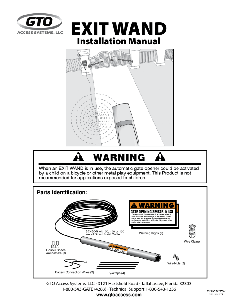
• from the point on the ground where you will run the wand cable into the control box, lay the wire out on a path as far as you can from the control box. The only difference between these wands is some of their features. Wand exit gate opener automatic loop detector wire underground.
The Only Difference Between These Wands Is Some Of Their Features.
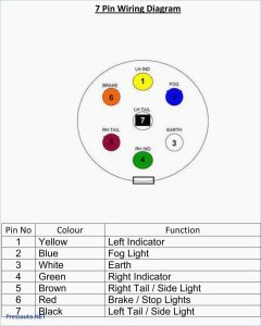
Blue black wiring diagram examples note: Led lights stop signal indicator directional signals signs systems directionalsystems. Wand exit gate opener automatic loop detector wire underground.
This Liftmaster La412U Wiring Diagram Exit Wand Diagram Has 720Px X 517Px.
Wiring diagram of the wand to the dk series sliding gate opener wiring diagram of the wand to the rk990&rk1200&ck1200 sliding gate opener (need to plug the adapter board to the. The wand should be no more than. Aleko® lm157 exit sensor underground automatic gate opener exit wand.
Push To Exit Button Wiring Diagram From S1.Manualzz.com Effectively Read A Wiring Diagram, One Offers To Learn How Typically The Components Inside The Program Operate.
The gto/pro wireless exit wand is. Usually ships in 24 to 48 hours. The exit wand is an electromagnetic sensor that detects metal mass in motion providing a 12 foot radius of detection that allows hands free exit from automatic gate operators.
Wiring Es… Kamis, 27 Oktober 2022 Edit.
Arkansas college of osteopathic medicine requirements (see gate instruction manual for complete instructions) braided ground from sensor cable. Gto exit wand instructions 09.18.14 3 4.
Wiring Exit Liftmaster La400 Wand Swing Estate.
This video is about driveway gate exit wands and exit loops and how they work.gatecrafters.com/?utm_source=youtube&utm_medium=contentlink&utm_campaign=drivew. Aftermarket keyless entry wiring diagram. Blue wire from the sensor cable to the exit terminal on the opener control board.