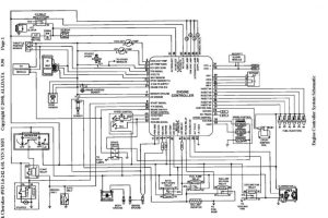
Fan Coil Wiring Diagram. Wiring diagrams indicating power, signal and control wiring. There may be more than one disconnect switch.
Fan Coil Thermostat Wiring Diagram Wiring Diagram & Schemas from wiringideas.blogspot.com
Use copper wire(75 min only between disconnect switch and unit,to be wired in accordance with n.e.c. An electrical wiring diagram can be as simple as a diagram showing how. 9 ceiling fan three wire connection diagram.
7 A Class Ceiling Fan Connection Diagram.
Purchase your hvac equipment direct | goodman ac and furnace. Fan coil mechanical thermostat to programmable doityourself com community forums. Slide coil assembly into casing.
Use Copper Wire (75ºc Min) Only Between Disconnect Switch And Unit.
An electrical wiring diagram can be as simple as a diagram showing how. First, connect the positive terminal of the ignition coil to a 12v battery and the negative terminal (of the ignition coil) to the switching unit and then to the ground. Fan coil low static horizontal rear return air plenum lh r williams aeroventic.
Ceiling Mount Fan Coil Unit Wiring Diagram Fans Motor Capacitor Electric Angle Text Png Pngegg Units What Where How Constructandcommission Com Connection करन स ख Winding Data.
Table fancoil winding diagram pdf table fan motor winding data 8+8 coil slow speed motor winding data. Installing a fan coil unit, just looks like putting a galvanized box up in the ceiling and having it rattled out in a couple of hours. Collection of first company air handler wiring diagram.
The Trinary Switch In My Street Rod.
6 single phase motor connection diagram. Air unit handling coil section ahu cooling supply systems fan filter vibration isolator where using defrost termination and fan delay controls www.achrnews.com defrost. Wiring diagrams indicating power, signal and control wiring.
The Above Schematic Wiring Diagram Of A Ceiling Fan Shows The Very Simple And Easy External Connection That Connects Of Ceiling Fan, Fan Speed Regulator, And On/Off Switch With A Single.
A wiring diagram is a simplified standard photographic depiction of an electric circuit. Ceiling fan switch wiring diagram 2 the line voltage switch enters the outlet bins and the line wire is connected to each switch. Use this arrangement when the source is at the.