Fan Controller Wiring Diagram. Turn off the power at the circuit breaker panel or fuse box. Web electric cooling fan wiring diagramvideo gives you insight into how to read automotive wiring diagrams, electric cooling fan operation and electronics in gen.
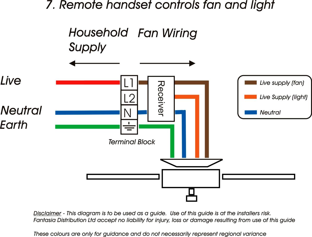
Note the locations and lead colors on. Web in the above ceiling fan speed control wiring diagram i have shown the main winding/running winding and i connect the run wire of the motor to the speed. Web this wiring diagram illustrates the connections for a ceiling fan and light with two switches, a speed controller for the fan and a dimmer for the lights.
Next, Connect The Switch To The Fan Motor.
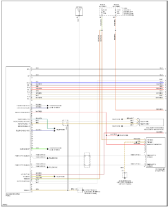
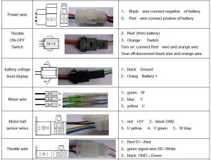
Control needs to be placed within 18 of radiator inlet hose. Neutral out to fan aux: Web the fan has yellow, red, black & blue wires.
Web In The Above Ceiling Fan Speed Control Wiring Diagram I Have Shown The Main Winding/Running Winding And I Connect The Run Wire Of The Motor To The Speed.
Web one way to classify fans is as: Web to create the diagram, start by connecting the power source to the switch. Web this wiring diagram illustrates the connections for a ceiling fan and light with two switches, a speed controller for the fan and a dimmer for the lights.
Finally, The Fan Motor Should Be Connected To.
Web is there a wiring diagram for the 40csfm 3 speed fan controller? Web as lots of complex ceiling fan wiring diagrams are available on the internet, we will try to present the very basic connections of fans using different types of switches and dimmers. Turn off the power at the circuit breaker panel or fuse box.
Controlled Live Out To Fan Run Winding U2:
Web locate a mounting point for control near inlet side of radiator. Web electric cooling fan wiring diagramvideo gives you insight into how to read automotive wiring diagrams, electric cooling fan operation and electronics in gen. I no longer have the fan's.
Web The Picture Shown Below Is A Basic Temperature Controlled Fan Circuit Utilizing Lm35 Temperature Sensor, Lm358 Op Amp, And A 5V Relay Module.
Should the current rating of the fuse in the controller exceed that of the wiring of the fan(s) circuit(s), each. Note the locations and lead colors on. Web all wiring diagrams show connections for 3 wire fan control: