Fan Switch Wiring Diagram . The black line, on the other hand, is. Here the exhaust fan is controlled by a timer instead of a switch.
Hampton Bay Ceiling Fan Switch Wiring Diagram Cadician's Blog from 2020cadillac.com 3 speed fan wiring diagram. We have usually seen in black wire 3 speed ceiling fan switch wiring diagram. Here the exhaust fan is controlled by a timer instead of a switch.
Source: tonetastic.info
We have usually seen in black wire 3 speed ceiling fan switch wiring diagram. Window type aircon wiring diagram.
Source: wholefoodsonabudget.com
Let’s draw a ceiling fan speed control switch wiring diagram: Effectively read a electrical wiring diagram, one offers to know how the components inside the system operate.
Source: stickerdeals.net
Wiring fan bathroom extractor pull cord wire diynot diy. Here the exhaust fan is controlled by a timer instead of a switch.
Source: stickerdeals.net
There should be two hot wires, black and red or both the same color, and. The black wire from the power cord will connect into the 2nd slot (off) on the switch on the.
Source: mrelectrician.tv
It does so based on the temperature information it receives from either your. The hampton bay ceiling fan wiring diagram starts with the power source.
Source: diy.stackexchange.com
It reveals the parts of the circuit as streamlined forms. Options include a manual pull switch, and a vacuum time lag.
Source: activediagram.abeteecologico.it
The wiring for this type of electrical connection looks like this: The extra load or the fan’s motor carries.
Source: akanecouvrett.blogspot.com
The hampton bay ceiling fan wiring diagram starts with the power source. The wiring for this type of electrical connection looks like this:
Source: wholefoodsonabudget.com
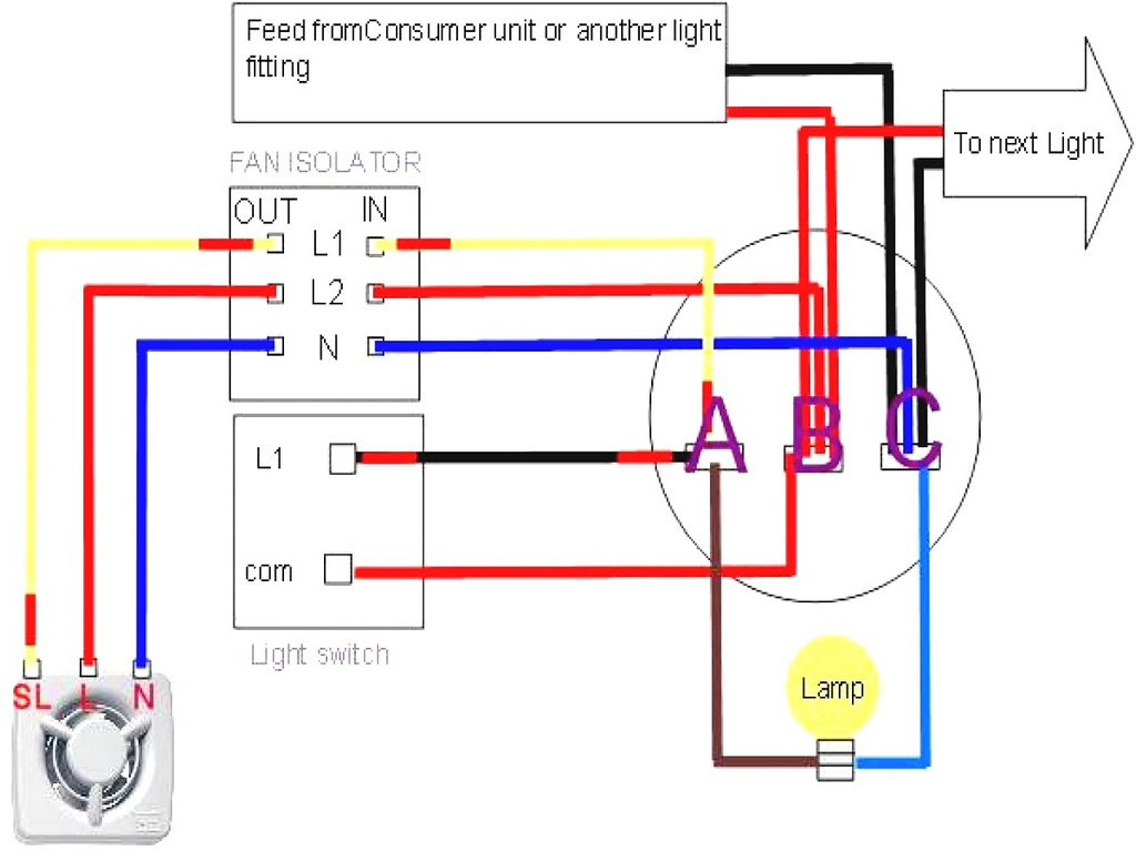
As you can see, we switched the hot line going to the light kit by inserting the switch. It can also be adapted for separate switching if required.
Source: 2020cadillac.com
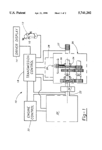
A cooling fan relay controls when the electric radiator cooling fan turns on and off. The wiring diagram above depicts the blue wire from the fan connected to the load wire from one switch.
Source: www.pinterest.com
It does so based on the temperature information it receives from either your. There should be two hot wires, black and red or both the same color, and.
Source: wholefoodsonabudget.com
A cooling fan relay controls when the electric radiator cooling fan turns on and off. Let’s draw a ceiling fan speed control switch wiring diagram:
Source: annawiringdiagram.com
The black wire from the power cord will connect into the 2nd slot (off) on the switch on the. The wiring for this type of electrical connection looks like this:
Source: wholefoodsonabudget.com
The supplied diagram below using dual relays with a single temp sensor is both the most reliable and easiest method we've found for. Free hampton bay reva7067b wire diagram.
Source: electronics.stackexchange.com
It reveals the parts of the circuit as streamlined forms. We have usually seen in black wire 3 speed ceiling fan switch wiring diagram.
Source: faceitsalon.com
The red wire from the motor will connect into the 3rd slot (hi) on the switch on the fan. Today i’m going to be talking about the ceiling fan speed control switch wiring diagram.
Source: faceitsalon.com
How to replace a hampton bay fan switch wire ceiling 2 sd from single latching swith connect or harbor breeze bulb lantern light 3 pull chain zing ear ze 208s e89885 kit wiring. Let’s draw a ceiling fan speed control switch wiring diagram:
Source: 3wayss.blogspot.com
A cooling fan relay controls when the electric radiator cooling fan turns on and off. We have usually seen in black wire 3 speed ceiling fan switch wiring diagram.
Source: faceitsalon.com
The wiring for this type of electrical connection looks like this: The black wire on the fan is connected to the other switch load wire.
Source: 2020cadillac.com
Diagram fan speed switch wiring schematic motor. Wiring fan bathroom extractor pull cord wire diynot diy.
Source: ricardolevinsmorales.com
These are compatible with most ceiling fans and most exhaust fans. There should be two hot wires, black and red or both the same color, and.
Source: alikadhamar.blogspot.com
Ceiling fan light kit wiring diagrams do it yourself help com. A cooling fan relay controls when the electric radiator cooling fan turns on and off.
Source: annawiringdiagram.com
The wiring diagram above depicts the blue wire from the fan connected to the load wire from one switch. 2 speed fan switch wiring diagram source:
Source: wiringdiagrams2.blogspot.com
There should be two hot wires, black and red or both the same color, and. For example , in case a module is usually.
Source: diagramweb.net
For example , in case a module is usually. 2 speed fan switch wiring diagram source:
Source: www.pinterest.pt
Today i’m going to be talking about the ceiling fan speed control switch wiring diagram. The black wire from the power cord will connect into the 2nd slot (off) on the switch on the.
Source: faceitsalon.com
Ceiling fan speed control switch wiring. The black wire on the fan is connected to the other switch load wire.
Source: 2020cadillac.com
Ceiling fan light kit wiring diagrams do it yourself help com. There should be two hot wires, black and red or both the same color, and.
Source: ask-the-electrician.com
A cooling fan relay controls when the electric radiator cooling fan turns on and off. 3 way fan switch diagram the function of this wire is to provide current from the switch to the electric motor of the fan.
Source: 2020cadillac.com
It reveals the parts of the circuit as streamlined forms. This wiring plan will simply run the fan when the room light is on.
The Extra Load Or The Fan’s Motor Carries.
The black wire from the power cord will connect into the 2nd slot (off) on the switch on the. Ceiling fan speed control switch wiring. There should be two hot wires, black and red or both the same color, and.
Today I’m Going To Be Talking About The Ceiling Fan Speed Control Switch Wiring Diagram.
Diagram fan speed switch wiring schematic motor. Schematic 3 speed fan motor wiring diagram database www.dentistmitcham.com. Here the exhaust fan is controlled by a timer instead of a switch.
Electric Fan Wiring Diagram With Relay.
It reveals the parts of the circuit as streamlined forms. 3 speed fan wiring diagram. Free hampton bay reva7067b wire diagram.
As You Can See, We Switched The Hot Line Going To The Light Kit By Inserting The Switch.
3 way fan switch diagram the function of this wire is to provide current from the switch to the electric motor of the fan. The hampton bay ceiling fan wiring diagram starts with the power source. These are compatible with most ceiling fans and most exhaust fans.
Effectively Read A Electrical Wiring Diagram, One Offers To Know How The Components Inside The System Operate.
It does so based on the temperature information it receives from either your. We have usually seen in black wire 3 speed ceiling fan switch wiring diagram. All circuits are the same ~ voltage,.