Field Controls Cas 4 Wiring Diagram. Rick ok, the wiring schematic weil gives us for this unit is. Page 1combustion air system model:
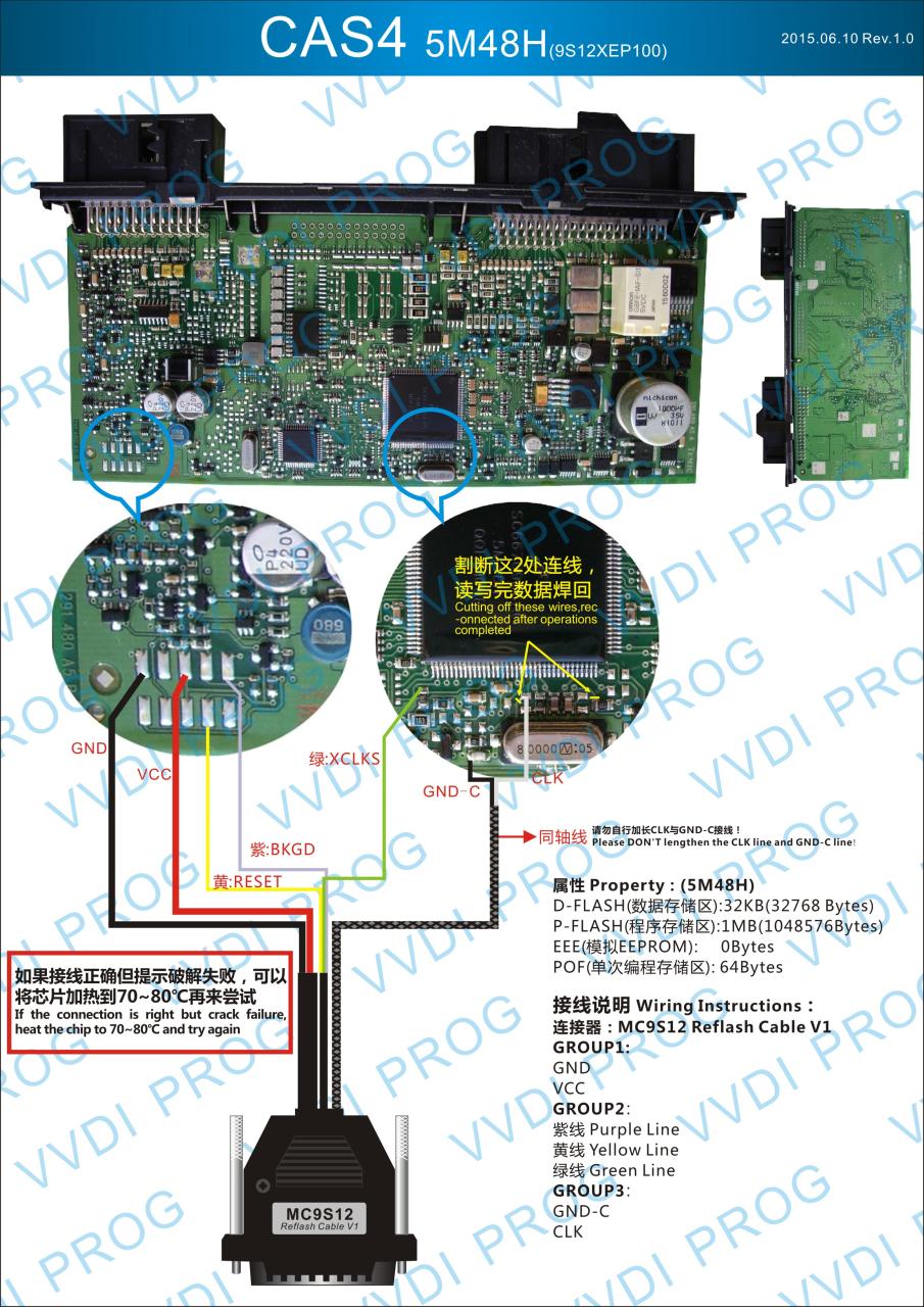
VVDIProg can be used as a CAS4+ programmer? from blog.uobdii.com
1) motorized blower 1) 4 galvanized intake air vent hood 2). View and download field controls 46371700 manual online. Internal wiring connections for the cas unit refer to figure 3 for the internal.
View And Download Field Controls 46371700 Manual Online.
View and download field controls 46261200 instruction sheet online. Wiring diagram of field instruments in control room in the following figure below there are various types of field instruments connected to the control room via a field junction box. 2) mounting brackets to secure the cas to a wall.
Page 1 120 Vac System Control Kit Model:
Up the cas system based on the size and length of the connecting ductwork and the input rating of the appliance. 46371700 fan pdf manual download. 1) motorized blower 1) 4 galvanized intake air vent hood 2).
User Manuals, Field Controls Fan Operating Guides And Service Manuals.
Page 1combustion air system model: Rick ok, the wiring schematic weil gives us for this unit is. 1) 4 galvanized intake air vent hood.
Download 199 Field Controls Fan Pdf Manuals.
2) wire/conduit connector(s) 1) 4 x 6 pipe increaser fitting. 46261200 fan pdf manual download. Refer to diagrams a and b for guidance in setting up the cas system based on the size and length of the connecting ductwork and the input rating of the appliance.
Internal Wiring Connections For The Cas Unit Refer To Figure 3 For The Internal.