Ford Regulator Wiring Diagram. Web by jean scraber | december 3, 2022 0 comment ford tractors have been around since the early 1900s, and they are still popular among farmers and hobbyists today. Web figure 2 shows a typical wiring diagram for this type of regulator.
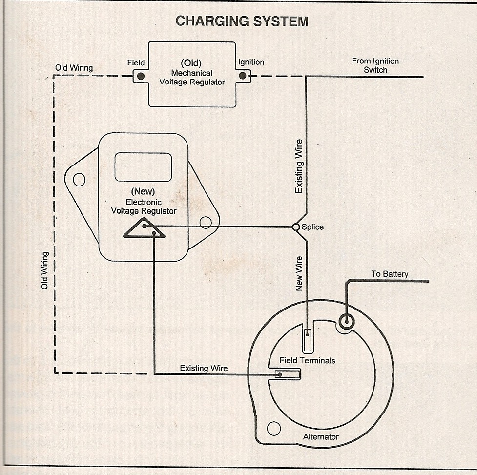
Figure 2 shows the i terminal connected to a warning light. Web ford external voltage regulator wiring diagram from www.sbmar.com. Each of these components is connected to the others through a series of wires.
See The Ford Voltage Regulator Wiring Diagram Images Below.
Web by jean scraber | december 3, 2022 0 comment ford tractors have been around since the early 1900s, and they are still popular among farmers and hobbyists today. Web to understand how your voltage regulator works, it's essential to first look at a ford voltage regulator diagram. When you employ your finger or perhaps the actual circuit along with your eyes, it is easy to mistrace the circuit.
And Also The Internal Wiring Diagram For The Alternator That Went.
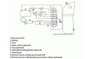
Web the portion of the wiring diagram that has to do with the voltage regulator is shown below, and shows the wiring locations and destinations. It helps to ensure the correct operation of the vehicle’s electrical system and provides safety for the driver. Web the symbols used on the diagram can vary depending on the manufacturer, but generally it will include the following:
Print The Cabling Diagram Off Plus Use Highlighters In Order To Trace The Routine.
It shows how these components are interconnected and how power travels from one to the other. Web ford voltage regulator wiring diagram. As technology has changed, so too have the wiring diagrams used to build and maintain ford tractors.
Knowing The Wiring Diagrams For A Ford External.
It includes the battery, alternator, starter motor, relay switch, and other. Web the wiring diagram for ford external voltage regulator is a critical part of any vehicle's electrical system. This diagram can help you understand how the electrical system in your truck works, and it can also help you.
The Positive Terminals Are Connected To The Positive Side Of The Alternator’s Output, While The Negative Terminals Are Connected To The.
These diagrams show the various different elements of your regulator, such as its input, output, and ground wires, along with the various. Each of these components is connected to the others through a series of wires. These include a voltage regulator, an alternator, a battery, and a starter.