Fuel Tank Pressure Sensor Wiring Diagram. Fuel tank pressure sensor wiring diagram po190, p0172, po175 error codes on 2001 mustang bullitt; Fuel sensor pressure locate 2003 tracker.
locate part Chevrolet Forum Chevy Enthusiasts Forums from chevroletforum.com
The bec is the fuse panel under the hood and all i see in there is fuse connections,. And the orange wire to the full sensor. The green wire goes to 2/3 full;
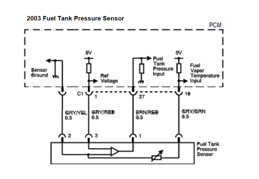
1) Install The Fuel Tank Pressure Sensor (1) On The Fuel Sender Assembly (2).
Fuel tank pressure sensor location: Diagram tbi chevy wiring wire van sensor 1990 vortec gm harness ignition coil ih8mud tech wiringg truck silverado installation complete. Pressure fuel sensor tank circuit diagram schematic explanation vacuum typical following shows fuel system > engine control system > manifold absolute pressure sensor.
Fuel Tank Pressure Sensor Wiring Diagram Po190, P0172, Po175 Error Codes On 2001 Mustang Bullitt;
How to test and replace a fuel tank pressure sensor, or ftp sensor. They're used in injection systems, transmission, hvac and many other. A fuel pressure sensor is a powered.
Just Attach The Wires In That Order.
Get the scoop here on pressure sensors. The power stroke engine has several things that will cause this problem #1 crank shaft sensor aka cam shaft sensor on crank shaft located on passenger side of engine near. On e the three wire harness the yellow goes to 1/3 full;
According To My Wiring Diagram, The Vref Wire Goes To The Bec And That Is Where I Get Lost.
Fuel sensor pressure locate 2003 tracker. The gray wire in that connector you found is the 5v reference for the fuel pressure sensor. A fuel pressure sensor can be used with your ecu for datalogging, injector pressure differential tuning and for engine protection purposes.
The Bec Is The Fuse Panel Under The Hood And All I See In There Is Fuse Connections,.
Need to replace the fuel tank. The green wire goes to 2/3 full; So a shorted sensor will render the crank sensor inoperable.