Gecko G540 Wiring Diagram. On the x axis, the cams are on the. Ready to plug and use, (115vac/230vac) brand new 4.
NowForever VFD E100 Series Wiring To Gecko G540 YouTube from www.youtube.com
To properly read a wiring diagram, one offers to know how the particular components in the method operate. Below are the wiring diagrams for 3dtek specific gecko g540 applications. Posted on 01/03/2019 by 3dtek.
Must Be A Male Db25 Connector.
Wiring diagram for a dyna 4400m m3 controller; Web this video explains the wiring diagram, required for installing limit/home switches in your g540 based cnc controller. The “x” sign means do not connect.
Web Gecko G540 Controller With 48V 12.5A Power Supply, Cooling Fan, Usb Connection Uc100, Or Use Ess Connection.
The following items are optional,. I have some projects coming up that will need a fourth axis, so i needed to buy a 4 axis motor controller. These may or may not.
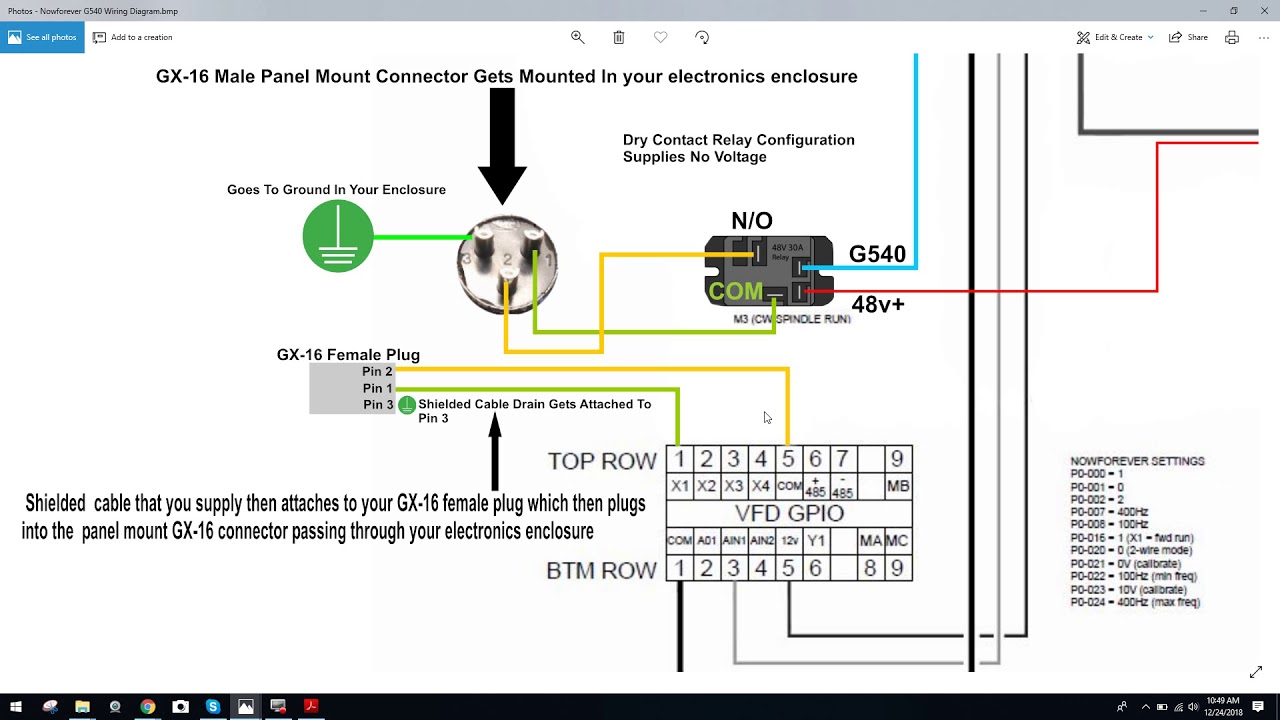
Web Gecko G540 Wiring Diagram Source:
I tried a cheap chinese toshiba. I have a trane xl1400 heat pump (model twy042b100a1) and. Posted on 01/03/2019 by 3dtek.
Web Gecko G540 Wiring Diagram.
Assuming your using mechanical micro switches not electronic. Web gecko wiring diagrams. The process covered in this video incl.
Ready To Plug And Use, (115Vac/230Vac) Brand New 4.
The g540 end of the cable. For example , if a module is powered. I am trying to get the x, y & z on the joysticks.