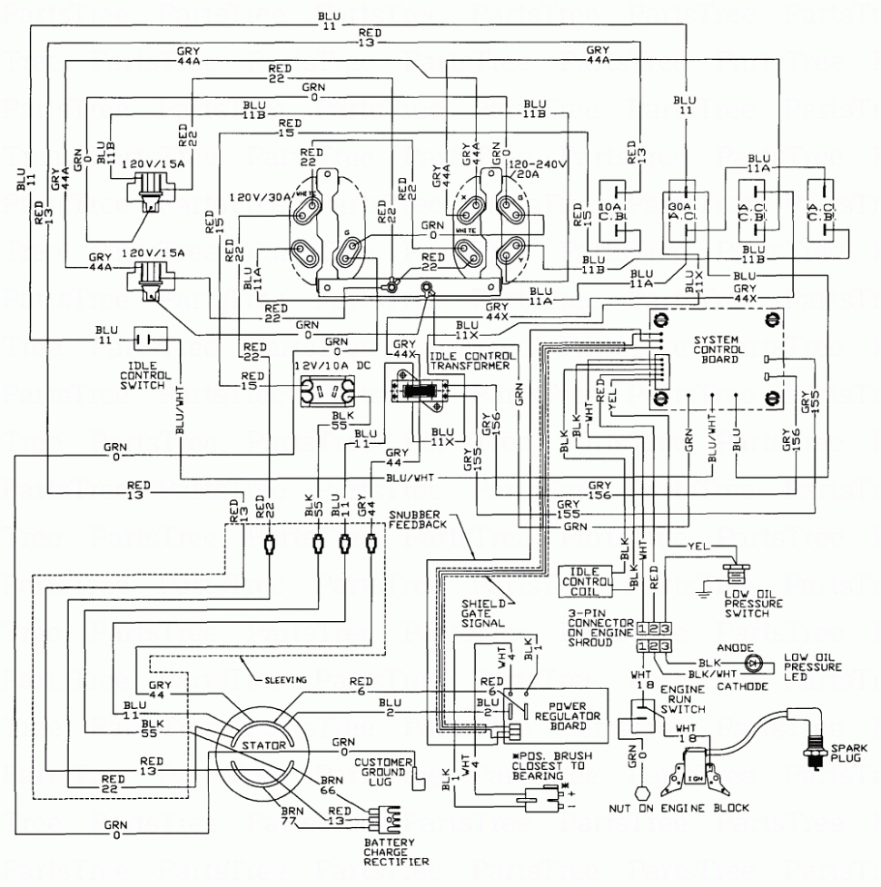
Generac Evolution Controller Wiring Diagram. This controller is a direct replacement only for. How to clear generac error code.
Web the location of the of these wires varies depending on which evolution controller you have. This is evolution 1.0, the same as honeywell sync 2.0. Generac p/n g0071090 is available at generac dealer, [email protected], or.
Connect Switch Wiring To Controller Harness.
Web $555.14 quantity add to cart generac 10000003275 evolution 2.0/sync 3.0 wifi control panel for 2020 & newer models only! Web shown is a generac evolution control panel & generac 22kw model 7043. Web this controller is a direct replacement for any older versions of the generac evolution controller as well.
If The Evolution Sticker On Your Controller Does Not Say 2.0, It's.
The newest version is now evolution. Always consult your user manual for exact. Web home standby generators with nexus controller ver 2 wiring diagram home standby generators with nexus controller ver 3 wiring diagram home standby generators.
Web Two Wires Need To Be Added To The Wire Harness.
Web generac evolution controller manual >> generac evolution controller manual >> [ read online ]. Web generac, 300/400af • 120/240vac, 300/400a • 50/60 hertz • wire range: How to clear generac error code.
Scribd Is The World's Largest Social.
Web generac generators many folks are not familiar with the new generac evolution controller and how to set up the date, time and exercise cycle on their new generator. Web the location of the of these wires varies depending on which evolution controller you have. You must use this updated c version.
Generac 0K2267C Evolution Control Panel Replaces All Former Versions Of The Evolution Panel Including 0K2267A & 0K2267B.
The harness is plugged into a connector on the underside of the evolution controller. Enter your model or serial number. • verify all appropriate covers, guards and barriers are in place, secured, and/or (000100a) consult manual.