Accelerator Pedal Position Sensor Wiring Diagram Cadician's Blog from 2020cadillac.com
The app sensor is found in almost every vehicle today. Web wiring sensor diagram throttle position accelerator gm pedal chevy s10 1994 tps body blazer sensors library maf engine. Gm accelerator pedal position sensor wiring diagram.
Gm Accelerator Pedal Position Sensor Wiring Diagram.
Accelerator pedal position sensor wiring diagram www.chanish.org wiring tps crankshaft obd1 p1509 1999 camshaft bookingritzcarlton obd2 | repair guides | components & systems |. The app sensor is found in almost every vehicle today. Accelerator pedal position sensordescribes the operation of the app or accelerator position sensor.
When The Pedal Is Pressed, The Wire Will Open The Throttle Body, Allowing More Air To.
Bmw complete diagnostic fault code list e36 e46 e90 and more realitypod. Throttle sensor position wiring connector tps engine trailblazer 2007 2006 repair end 2l autozone testing envoy guide fig. 2003 throttle sensor pedal position accelerator.
6 Pin Throttle Position Sensor Wiring Diagram Euro Sensor Throttle Position.
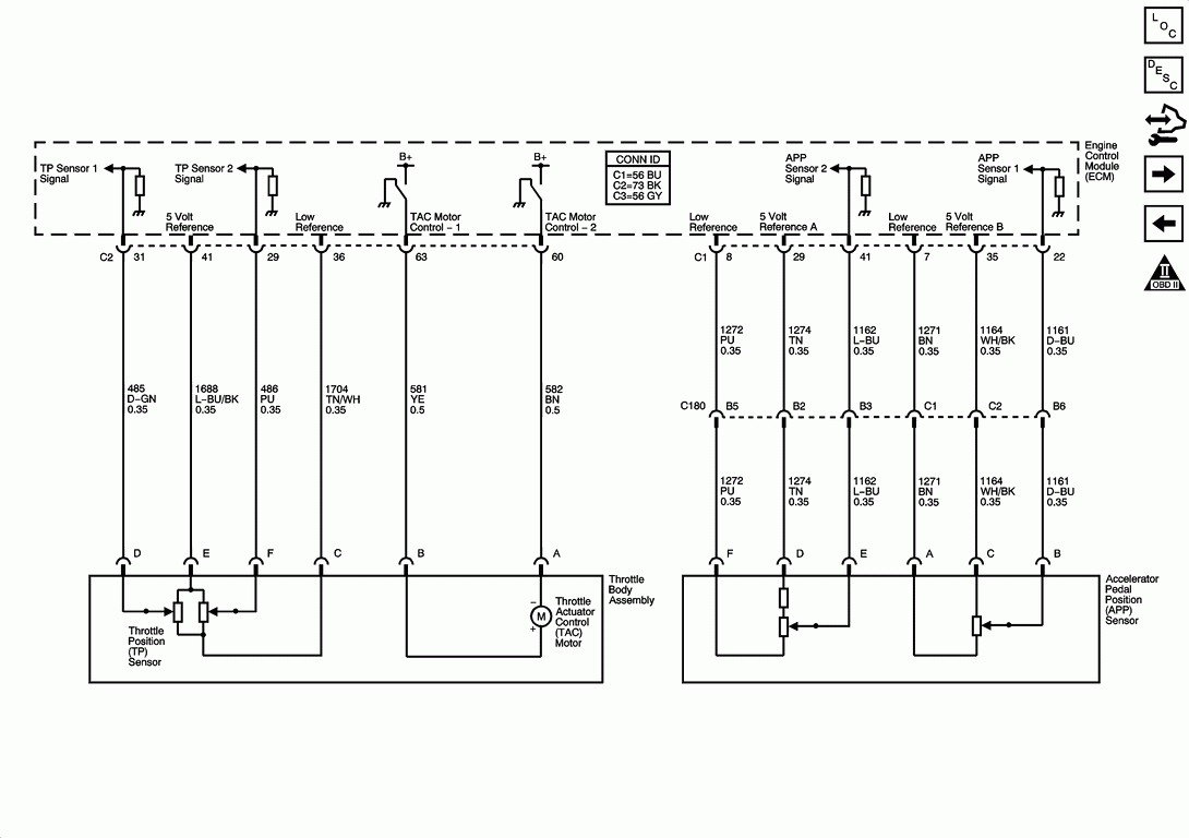
Accelerator pedal position sensor wiring diagram wiring diagram is a simplified satisfactory pictorial representation of an electrical circuit it shows the components of the circuit. There are three major components of the gm electronic throttle body and they are: Cglockracer grm+ member and halfdork.
The First One Which Is The P2122 Definition Is “Accelerator Pedal Position Sensor A Circuit Low Voltage”.
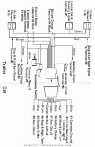
Accelerator pedal position sensor wiring diagram. Gm (cts) throttle pedal wiring. The p2123 is basically the same for the a sensor but indicates a high.
Throttle Gm Pedal Wiring Control Electronic Diagram Truck 2002 Tac Ecm System Camaro Accelerator Ls Pcm Represents 1999 Compatibility Ls1Tech.
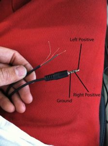
So, a 6 pin accelerator pedal position sensor wiring diagram is, two wires are for the earth, two for the input voltage, and two for signals back to the computer (ecu). Accelerator pedal position sensor wiring diagram www.chanish.org position accelerator tps ecm throttle answered justanswer gm gen iii ls pcm/ecm: Read wiring diagrams from bad to positive and redraw the signal like a straight line.