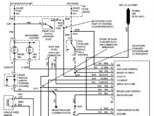
Greddy Boost Gauge Wiring Diagram. Red = 12v orange = ignition switch source yellow = parking light i was going to use the seat heater fuse. Vehicle with factory boost controlling solenoid valve dual port actuator disconnect the connector and the vacuum lines off from the.
Because mine is mechanical, it. Web boost greddy pressure sensor boost n/a n/a n/a connector emanage wiring table 1 1 ignition 2. Web greddy is back with their new multi d a gauges evolutionm mitsubishi lancer and evolution community.
Then You Can Plug In The.
We will also go into detail. Web greddy is back with their new multi d a gauges evolutionm mitsubishi lancer and evolution community. Web page 5 wiring diagram the wires coming out form the key switch usually consist of:
Web So I Am Having Trouble Understanding The Power Wiring Diagram For My Electrical Egt And Boost Gauges.
Vehicle with factory boost controlling solenoid valve dual port actuator disconnect the connector and the vacuum lines off from the. Greddy connectors on each end of the cut wire. Because mine is mechanical, it.
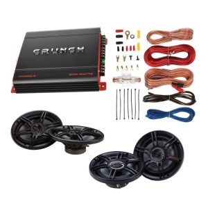
Racing Gauge Greddy Multi D/A Lcd Digital Display Car Gauge Turbo Boost Gauge,.
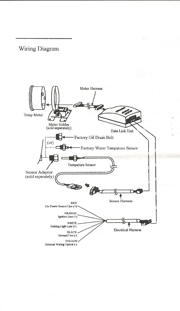
Web the greddy instruction manual has 3 power wires: Tap the hose for the electronic sensor into the hose that runs from the intake. Spd b/c rpm 12 volt ignition.
(1) Remove The Cover Under The Glove Box To Access The Ecu And Ecu Harness.
Most gauges will have three to four wires, depending on the type of gauge. Manifold to the solenoid that. Web in this article, we will cover wiring diagrams and explain how they allow the components of a greddy boost controller to function correctly.
Web I Just Received My Greddy 52Mm Electrical Boost Gauge And Need Some Help Finding Where I Can Tap Into An Igniton Wire.
Evasive motorsports greddy sirius turbo. Does anyone have a wiring diagram? Web the most important part of this will be the wiring diagram.