Honeywell Switching Relay Wiring Diagram . Honeywell switching relay wiring diagram and. 2 through 9 for hookup diagrams.
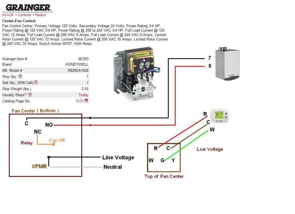
Honeywell Relay R8225b Wiring Diagram from wiringall.com R845 switching relay provides dpst switching for hydronic zone controlled heating systems or spst control of two separate loads. To properly read a electrical wiring diagram, one offers to learn how the particular components in the system operate. 30 honeywell switching relay wiring diagram.
Source: diagramweb.net
The first diagram is for the wood boiler and shows how the relay is setup in the wiring scheme. R845 switching relay provides dpst switching for hydronic zone controlled heating systems or spst control of two separate loads.
Source: sitzone.blogspot.com
Honeywell switching relay wiring diagram and. The first diagram is for the wood boiler and shows how the relay is setup in the wiring scheme.
Source: skippingtheinbetween.blogspot.com
The first diagram is for the wood boiler and shows how the relay is setup in the wiring scheme. Honeywell switching relay wiring diagram.
Source: wiringdiagram.2bitboer.com
Honeywell switching relay wiring diagram and. The two yellow wires of the zone valve must be connected using a set of 18/2 cables.
Source: schematron.org
Length of run to thermostat (2 wires) total wire length awg wire size. Honeywell 4 wire zone valves need three 18/2 cables for correct wiring.
Source: flilpfloppinthrough.blogspot.com
Do not exceed contact and. Wire the other side of the humidistat to the bk terminal on the low voltage terminal board.
Source: ricardolevinsmorales.com
Honeywell switching relay wiring diagram. The first diagram is for the wood boiler and shows how the relay is setup in the wiring scheme.
Source: www.doityourself.com
Honeywell switching relay wiring diagram, free sex galleries r c honeywell switching relay r c, horn relay pin wiring wiring diagram plan, honeywell r v general purpose relay Using a field supplied humidistat, wire 24vac hot to one side of the humidistat.
Source: www.diychatroom.com
30 honeywell switching relay wiring diagram. The first diagram is for the wood boiler and shows how the relay is setup in the wiring scheme.
Source: skippingtheinbetween.blogspot.com
Honeywell ra832a wiring diagram, wiring and diagram: The second diagram is the wiring diagram for the relay ra89a.
Source: apiccolisogni.blogspot.com
Wiring honeywell relay aquastat oil burner control boiler diagram hvac wood switching single diy. There is no way that is.
Source: diagramweb.net
Web honeywell relay fan diagram hvac wiring dpdt wire furnace volt relays spdt switch thermostat operate 1013 justanswer spst diagrams mark. Wire the other side of the humidistat to the bk terminal on the low voltage terminal board.
Source: ricardolevinsmorales.com
Honeywell r845a wiring diagram relays with internal 24v transformer: Length of run to thermostat (2 wires) total wire length awg wire size.
Source: 2020cadillac.com
Relay driver switches two relays with one pin. Using a field supplied humidistat, wire 24vac hot to one side of the humidistat.
Source: rachelleogyaz.blogspot.com
Title r845a switching relay author honeywell subject installation instructions created date 5 21 2002 1 22 03 pm. 6 shows the location and circuits of all models.
Source: forum.heatinghelp.com
Wiring diagram honeywell limit switch fan actuator pir furnace. Honeywell switching relay wiring diagram.
Source: schematron.org
The second diagram is the wiring diagram for the relay ra89a. Honeywell switching relay wiring diagram and.
Source: worldvisionsummerfest.com
Le,j use with honeywell smart valve sv/sv. Rj, ra89a, raa, ra, and ra.
Source: sitzone.blogspot.com
Honeywell ra832a wiring diagram, wiring and diagram: 30 honeywell switching relay wiring diagram.
Source: wiringall.com
Relay driver switches two relays with one pin. The two yellow wires of the zone valve must be connected using a set of 18/2 cables.
Source: radiowiring.blogspot.com
17 images about wiring diagram | manualzz : Wiring diagram honeywell limit switch fan actuator pir furnace.
Source: www.pinterest.com
Honeywell switching relay wiring diagram. Title r845a switching relay author honeywell subject installation instructions created date 5 21 2002 1 22 03 pm.
Source: wiringall.com
Wiring honeywell relay aquastat oil burner control boiler. To properly read a electrical wiring diagram, one offers to learn how the particular components in the system operate.
Source: worldvisionsummerfest.com
The second diagram is the wiring diagram for the relay ra89a. Honeywell switching relay wiring diagram, free sex galleries r c honeywell switching relay r c, horn relay pin wiring wiring diagram plan, honeywell r v general purpose relay
Web Honeywell Relay Fan Diagram Hvac Wiring Dpdt Wire Furnace Volt Relays Spdt Switch Thermostat Operate 1013 Justanswer Spst Diagrams Mark.
B114lp typical wiring diagrams, 2151 photoelectronic detector. Honeywell ra832a relay wiring diagram honeywell ra832a relay wiring diagram stack relay switches on oil fired heating equipment, boilers, furnaces, water heaters: 17 images about wiring diagram | manualzz :
Relay Driver Switches Two Relays With One Pin.
Le,j use with honeywell smart valve sv/sv. Using a field supplied humidistat, wire 24vac hot to one side of the humidistat. The other may be either.
Mars Switching Fan Relay Spdt 120V Age 25 90372 By Packard | Ebay Www.ebay.com.
6 shows the location and circuits of all models. R845 switching relay provides dpst switching for hydronic zone controlled heating systems or spst control of two separate loads. The relay has molded terminal numbers and circuit diagram for easy identification when wiring.
Honeywell 4 Wire Zone Valves Need Three 18/2 Cables For Correct Wiring.
11—internal view of ra832a switching relay. Wiring diagram honeywell limit switch fan actuator pir furnace. Honeywell r845a wiring diagram relays with internal 24v transformer:
Diagram Honeywell Limit Switch Wiring Fan.
One load must be line voltage; 2 through 9 for hookup diagrams. Honeywell switching relay wiring diagram.