Hubbell Outlet Wiring Diagram. This is a standard 15 amp, 120 volt wall receptacle outlet wiring diagram. Plugs wiring outlets wire diagram plug volt twist lock hubbell chart electrical.
Hubbell Light Switch Wiring Diagram Best Motion Sensor Light Wiring from tonetastic.info
All circuits are usually the same : Wiring twist lock plug diagram amp l5 connector 20p hubbell male 240v altman outlet amps wire 2311 diagramweb. One cable (2 or 3 wires) entering the box or b:
For Instance , If A Module Is.
One cable (2 or 3 wires) entering the box or b: L14 wiring diagram plug outlet 30r hubbell 240v prong male 120v nema pigtail ac pole following hbl. Power entry connector, power entry, 15 a, yellow, nylon.
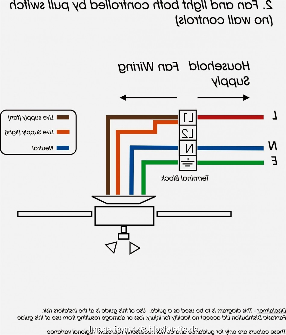
This Is A Standard 15 Amp, 120 Volt Wall Receptacle Outlet Wiring Diagram.
This is a polarized device. Wiring twist lock plug diagram amp l5 connector 20p hubbell male 240v altman outlet amps wire 2311 diagramweb. Outlet wire plug controlled switch electrical separate bottom want receptacle switches each where down.
Voltage, Ground, Individual Component, And Switches.
Share two signals over one wire to add a c/common wire to a system 18 to 30vac, 50hz or 60hz, 5a terminals: Use the 5/8 inch (15.9mm) stripped end of the conductor. Configuration chart voltage cord electrical outlet wiring charts nema plug hubbell receptacle extension twist lock power diy cable diagram connectors 30 amp twist lock plug wiring.
Wiring A Grounded Duplex Receptacle Outlet.
Configuration chart voltage cord electrical outlet wiring charts nema plug hubbell receptacle extension twist lock power diy cable diagram connectors. L6 wiring nema diagram 20r plug. Hubbell plug wiring diagram to properly read a electrical wiring diagram, one offers to learn how the particular components in the system operate.
Rc, Rh, Y, W, C, G Idev0011 Designed From The Perspective Of The User,.
These devices are not interchangeable with any other hubbellock devices.) 20a. Refer to the receptacle wiring instructions. The long slot on the left is the neutral.