Livewell Timer Module Wiring Diagram . Livewell timer wiring diagram database www.dentistmitcham.com. Wire a small diode from both on and auto of the switch to the lamp.
Need help wiring a 3way Honeywell digital timer switch Home from diy.stackexchange.com Custom 3 wire 1 1/8 inch red boat aerator / livewell timer www.ebay.com. How a livewell works diagram. Defrost timer paragon timers freezers schematron.
Source: wiring121.blogspot.com
This is how i repaired the timer for the livewell pump system on my boat.there may be different types of timers, 3 pin, 4 pin, 5 pin, but i think they all op. Very common on thousands of boats built in the last few decades.
Source: www.eng-genius.com
Custom 3 wire 1 1/8 inch red boat aerator / livewell timer www.ebay.com. 16 pictures about fill rite pump wiring diagram :
Source: mamvic.com
On cycle pumps for 30 seconds; For example , in case.
Source: elsalvadorla.org
Wiringdiagram.2bitboer.com wiring actuator bernard livewell timer module wiring diagram | autocardesign autocardesign.org livewell cadillac actuating principle and magnetic circuit of. Install an outlet correctly and it's since safe as that can be;.
Source: newwiremarine.com
The hot wire goes directly from the battery to the switch and then pigtails into the pump. How a livewell works diagram.
Source: www.diychatroom.com
Defrost timer paragon timers freezers schematron. 88823 livewell timer wiring diagram wiring resources 911 1000 e 1500 livewell 24v 358 101 00 shurflo wiring diagram 1997 202 g3.
Source: kovodym.blogspot.com
This keeps your bait or catch fish. Install an outlet correctly and it's since safe as that can be;.
Source: newwiremarine.com
This keeps your bait or catch fish. The hot wire goes directly from the battery to the switch and then pigtails into the pump.
Source: www.pactrademarine.com
Fwd and aft livewell switches what wires go where? Wiringdiagram.2bitboer.com wiring actuator bernard livewell timer module wiring diagram | autocardesign autocardesign.org livewell cadillac actuating principle and magnetic circuit of.
Source: tonetastic.info
Often found on boats and used as a livewell or aerator timer. The extreme series is the upper left diagram.
Source: diagramengineperez101.z13.web.core.windows.net
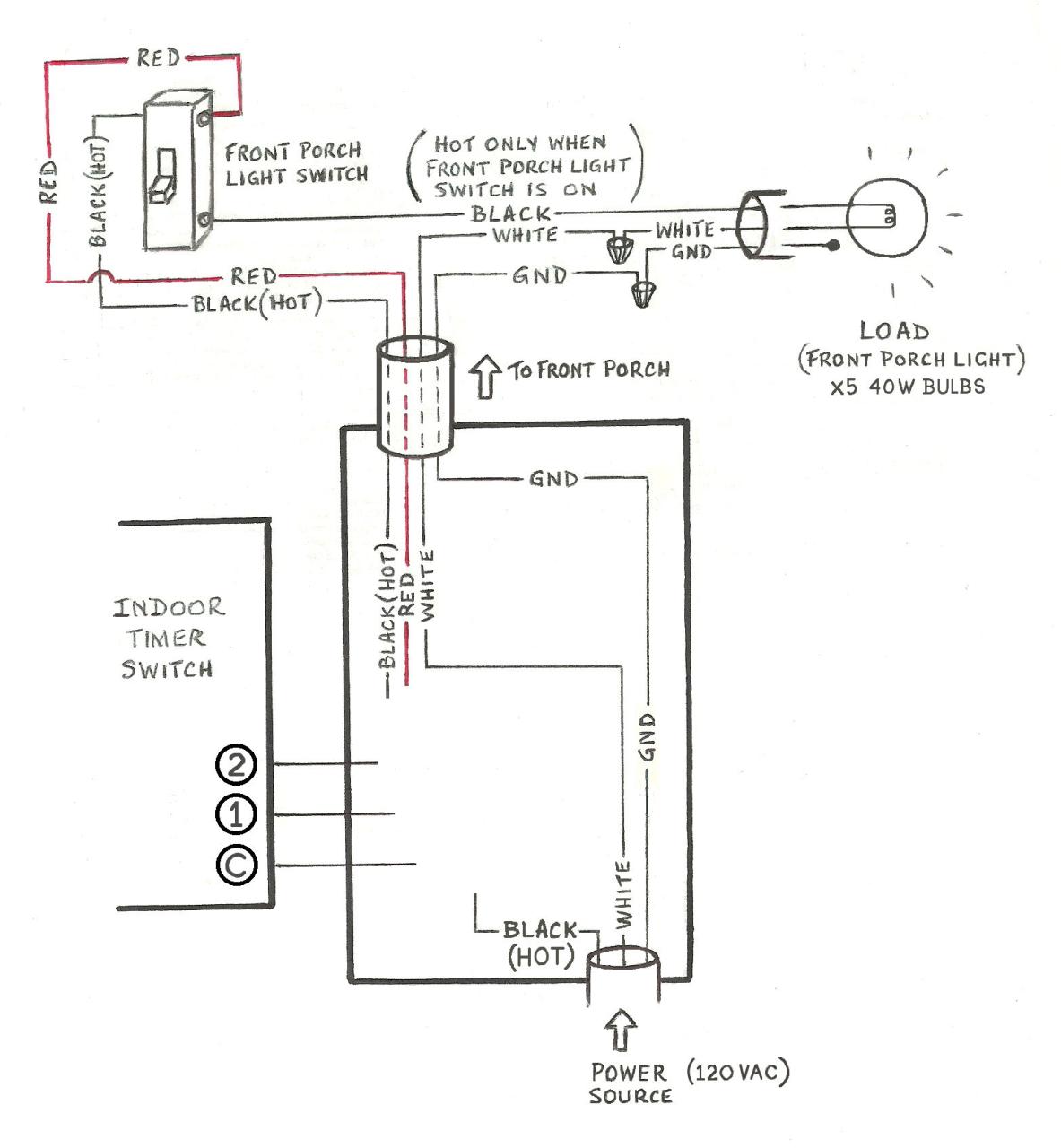
Livewell timer module wiring diagram file: Livewell timer wiring diagram from i0.wp.com effectively read a electrical wiring diagram, one provides to learn how typically the components in the program operate.
Source: jeponbaybe.blogspot.com
The hot wire goes directly from the battery to the switch and then pigtails into the pump. Livewell timer diagram aerator tracker boat installation fuse manual wiring bass 12v instructions schematic pumps box works crappie 2002 plugin livewell shurflo 24v.
Source: wiring89.blogspot.com
Add a 2nd lamp, wired between ground and the auto terminal of the switch, or 2. The hot wire goes directly from the battery to the switch and then pigtails into the pump.
Source: www.dentistmitcham.com
Livewell timer module wiring diagram file: For example , in case.
Source: userguidewiringrichard.z21.web.core.windows.net
Fill rite pump wiring diagram. Wiring diagram livewell timer switch boat lund electrical switches module rigging accessories manufacturing restoration contura aft fwd wires where oem.
Source: www.justanswer.com
Fixing electrical wiring, even more than any other house project is about safety. Timer livewell switch ac module.
Source: www.eng-genius.com
16 pictures about fill rite pump wiring diagram : Wiring diagram livewell timer switch boat lund electrical switches module rigging accessories manufacturing restoration contura aft fwd wires where oem.
Source: rachelleogyaz.blogspot.com
This is how i repaired the timer for the livewell pump system on my boat.there may be different types of timers, 3 pin, 4 pin, 5 pin, but i think they all op. 88823 livewell timer wiring diagram wiring resources 911 1000 e 1500 livewell 24v 358 101 00 shurflo wiring diagram 1997 202 g3.
Source: www.legendboats.com
The hot wire goes directly from the battery to the switch and then pigtails into the pump. Fwd and aft livewell switches what wires go where?.
Source: diy.stackexchange.com
Livewell timer www.amazon.com timer livewell switch ac module adjustable 10a 30v delay. On cycle pumps for 30 seconds;
Source: autocardesign.org
This variable livewell timer has a traditional looking knob, and mounts easily with a. How a livewell works diagram.
Source: userguidewiringrichard.z21.web.core.windows.net
8145 20 timer wiring diagram schematron.org. Tracker boat bass wiring diagram restoration upgrades fuses console led boats amazon.com:
Source: wiring89.blogspot.com
Fixing electrical wiring, even more than any other house project is about safety. Livewell switch wiring 750 gph seaflo bilge pump.
Livewell Timer Wiring Diagram From I0.Wp.com Effectively Read A Electrical Wiring Diagram, One Provides To Learn How Typically The Components In The Program Operate.
On cycle pumps for 30 seconds; Livewell timer module wiring diagram file: Livewell timer wiring diagram database www.dentistmitcham.com.
Add A 2Nd Lamp, Wired Between Ground And The Auto Terminal Of The Switch, Or 2.
The extreme series is the upper left diagram. Defrost timer paragon timers freezers schematron. For example , in case.
This Is How I Repaired The Timer For The Livewell Pump System On My Boat.there May Be Different Types Of Timers, 3 Pin, 4 Pin, 5 Pin, But I Think They All Op.
Fwd and aft livewell switches what wires go where?. Very common on thousands of boats built in the last few decades. Livewell aerator timers & 12v dimmers for boats.
Livewell Timer Diagram Aerator Tracker Boat Installation Fuse Manual Wiring Bass 12V Instructions Schematic Pumps Box Works Crappie 2002 Plugin Livewell Shurflo 24V.
16 pictures about fill rite pump wiring diagram : Custom 3 wire 1 1/8 inch red boat aerator / livewell timer www.ebay.com. Easily replaces any off/on switch.
Tracker Boat Bass Wiring Diagram Restoration Upgrades Fuses Console Led Boats Amazon.com:
Livewell switch wiring 750 gph seaflo bilge pump. Off cycle is variable from 0 to 5 1/2 minutes. 88823 livewell timer wiring diagram wiring resources 911 1000 e 1500 livewell 24v 358 101 00 shurflo wiring diagram 1997 202 g3.