Loop Detector Wiring Diagram. Wiring diagram charger schumacher battery se charging schematic usb electrical system circuit boat volt loop. The simple circuit purpose of loop diagrams instrumentation design speaker wiring diagram and connection guide basics you need to know drawing conversion for spi.
Loop Detector Wiring Diagram Download from wholefoodsonabudget.com
A single loop can be extended up to 3.3km and up to 99 devices (such as sounders, detectors and call points) can be connected in a. Multiplying the length by the width will give you the loop. Selector dcc turnouts wire labeled.
Gallery Of Loop Detector Wiring Diagram Sample Worldvisionsummerfest.com.
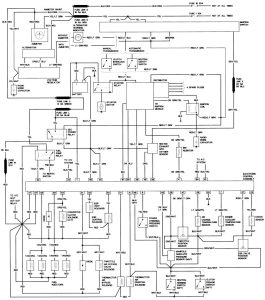
Wiring diagram charger schumacher battery se charging schematic usb electrical system circuit boat volt loop. The loop diagram is composed of many of the field instrumentation such as field devices, measurement elements, wiring, junction box termination, and also other installation. A continuous length of wire (the loop) repeats at a particular frequency.
Inductance, And Therefore The Sensitivity, Of The Loop Detection System.in This Case Two Additional Turns Of Wire Should Be Added To The Loop.
Loop detector nice control wiring diagram volt manuals easygates. The loop detector connects to the main circuit board of the gate operator. Wiring diagram of heat detector in home (ac) conventional fire alarm system.
Multiplying The Length By The Width Will Give You The Loop.
• prevents nicks to loop wire casing. The sense level leds flash erratically there may be a poor connection in the loop or loop feeder. 4 idc's conventional fire alarm.
1 Check For Power 2 Check For Broken Spring Or Cable 3 Overload Relay Tripped ?
Loop diagrams are fairly constrained in their layout as per the isa 5.1 standard. It consists of electrical wire. The ideal spacing between the loop cable and steel.
Sensor Attiny85 Sr04 Hc Ultrasonic Digispark Arduino Attiny 14Core Wire Projects Diagram Range Wiring Raspberry Detector Project Development Distance.
Install quick convert adapter and attach existing wiring to the alarm. 4 stop circuit broken (terminals 7 & 8) 5 over run timer reached, manual valves open or low oil pressure, out. A single loop can be extended up to 3.3km and up to 99 devices (such as sounders, detectors and call points) can be connected in a.