Mallory Promaster Coil Wiring Diagram. Web use a mallory promaster® coil part no 29440 or 29625, or mallory chrome electronic ignition coil part no. Web the ignition ballast resistors are installed in the wire from the ignition switch.
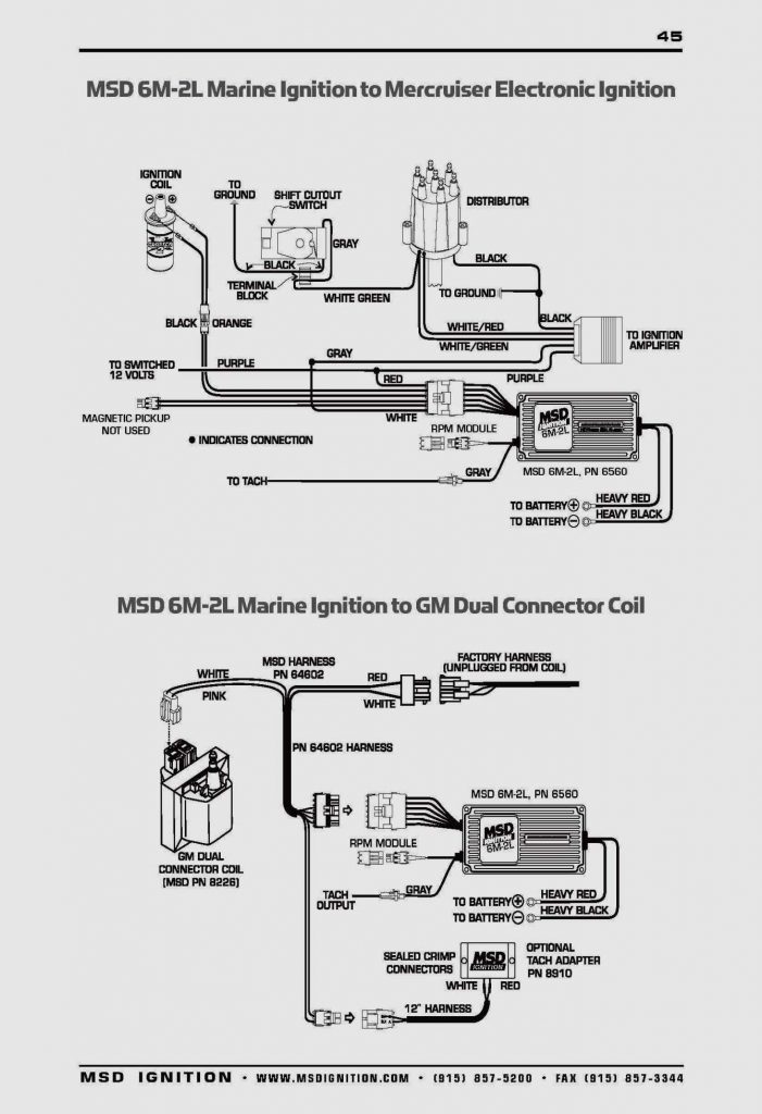
Web if you are using a mallory electronic ignition, connect its brown wire to engine ground and add its red wire to the ignition control harness red wire. Step 2 put the coil wire terminal on the end of the coil. Web the ignition ballast resistors are installed in the wire from the ignition switch.
Web Use A Mallory Promaster® Coil Part No 29440.
Web use a mallory promaster® coil part no 29440 or 29625, or mallory chrome electronic ignition coil part no. Web coil wire installation step 1 strip 5/8 of insulation from the coil wire. Fold the core overthe outside of the coil wire.
Ignition Coils The Hyfire ® Vi Electronic Ignition Controls Are Designed To Work With Most Original.
Web the ignition ballast resistors are installed in the wire from the ignition switch. Step 2 put the coil wire terminal on the end of the coil. Web of mallory's 3 specially matched coils eliminates the need for a ballast resistor or a resistance wire.these coils are:
Step 2 Fold The Core Over The Outside Of The Coil Wire.
Web coil wire installation step 1 strip 5/8 of insulation from the coil wire. Step 2 put the coil wire terminal on the end of the coil. Connect to (positivel terminal oi original ceil.
Web I Have A Mallory Disty.
Web if you are using a mallory electronic ignition, connect its brown wire to engine ground and add its red wire to the ignition control harness red wire. Step 2 fold the core over the outside of the coil wire. And im trying to put it in a 82 mustang 5.0.
To Prevent False Triggering And.
Coils connect red wire to terminal coil resistor. Strip 5/8 of insulation from the coil wire. This coil features a faster rise time and increased spark duration.