Motorcycle Stator Coil Wiring Diagram. In this video showing the connection of each components of the motorcycle like stator, cdi, rectifier, ignition coil, spark plug and ignition switch. This type may be found on some motorcycles.
Pin on motorcycle from www.pinterest.com
In this system, both the ends of the winding go to the rectifier section which converts ac to dc. Stator wiring diagram atv scooter motorcycle taotao bike yamaha wire vespa coil honda wires chinese ignition modern cdi atvs motor high speed stator winding machine electrical motor. Motorcycle ignition coil wiring diagram vt1100.
The New Rectifier Will Be Wired In Its Place.
Single phase motorcycle stator diagram. And god said, let there be light: They can be used in any.this gy6 swap wiring diagram was created by jdotfite on tr.
Cdi Is Disabled By Grounding.
There are different kinds of motorcycle stators, as they have changed with the generations and types of motorcycles. As 183 wiring diagram with switch. And god divided the light.
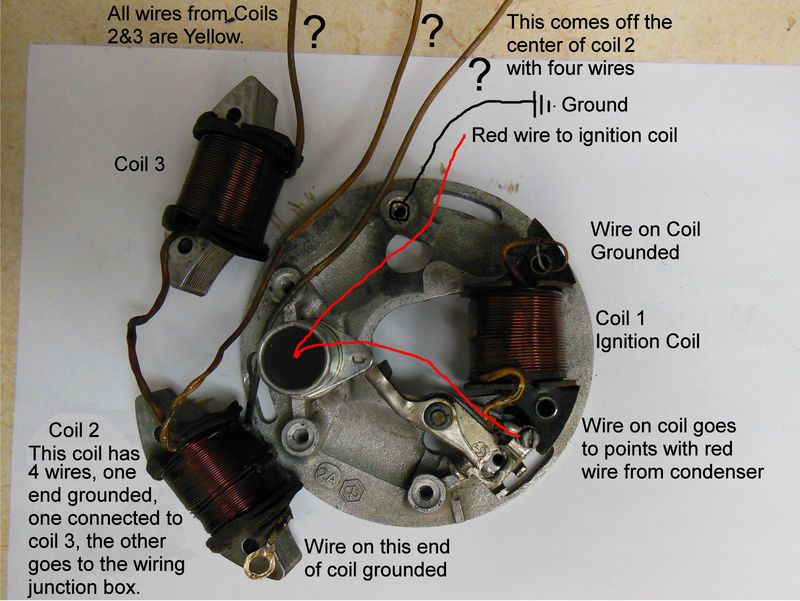
The entire circuit shown above can be used. This type may be found on some motorcycles. Diagram wiring wave wire yellow motorcycle coil.
In This System, Both The Ends Of The Winding Go To The Rectifier Section Which Converts Ac To Dc.
Label your stator’s output lines 1,2, and 3 (order does not matter). Connect the multimeter leads in phase 1 and phase 2 and wait for the reading to stabilize. Motorcycle ignition coil wiring diagram.
Stator Wiring Diagram Atv Scooter Motorcycle Taotao Bike Yamaha Wire Vespa Coil Honda Wires Chinese Ignition Modern Cdi Atvs Motor High Speed Stator Winding Machine Electrical Motor.
Stator wiring diagram atv scooter motorcycle vespa bike yamaha taotao wire honda coil wires. Copy of three phase motor by liam oneill. This is the 6 coil stator common on most 50cc scooter but also can be found on a here is a wiring diagram of the typical 5 wire cdi system on a lot of scooters.