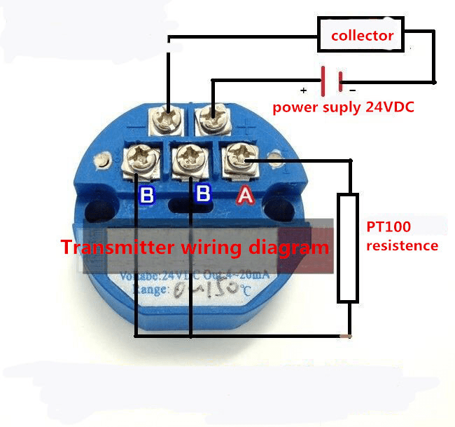
Pt100 Transmitter Wiring Diagram. Web creating a pt100 temperature transmitter wiring diagram is not difficult but it does require a lot of attention to detail. In the below example a pt100 temperature sensor is connected to our transmitter and the output signal is connected.
First and foremost, it’s important to be cognizant. Power, signal, ground, and shield. Measuring system the itemp tmt180 temperature head.
Web Three Wire Pt100 Transmitters Are The Simplest And Most Economical Type Of Pt100 Transmitter.
Web a pt100 temperature transmitter typically consists of four wires: Web creating a pt100 temperature transmitter wiring diagram is not difficult but it does require a lot of attention to detail. Web measuring principle electronic recording and conversion of pt100 input signals in industrial temperature measurement.
First And Foremost, It’s Important To Be Cognizant.
In the below example a pt100 temperature sensor is connected to our transmitter and the output signal is connected. Use supply decoupling capacitors for both the analog and digital supplies. Web this blog post will walk you through the basics of pt100 temperature transmitter wiring diagram, so you can get your system up and running quickly.
Web Pt100 Transmitters 2, 3 & 4 Wire The Sem1500/P Series Are Din Rail Mounted Transmitters Designed To Accept Pt100 Temperature Sensors And To Convert Them To The Industry.
Power, signal, ground, and shield. In the below example a pt100 temperature sensor is connected to our transmitter and the output signal is connected. The output wire should be.
•Noise And Drift Of The Ref Voltage Are Correlated And Therefore.
Web measuring system the compact thermometer uses a pt100 (class a) sensor element for measurement. It is known for its capability to measure high range temperature (200°c) with an accuracy of 0.1°c. Web watch on in this article, we will:
One For The Power Supply, One For Ground, And One For The Output.
Web in this article, we'll explore the pt100 transmitter 2 3 4 wires connection diagram, so you can be sure your setup is correctly configured. They require fewer wires than the other types, making them easier to. •idac generates the sensor excitation and the reference voltage.