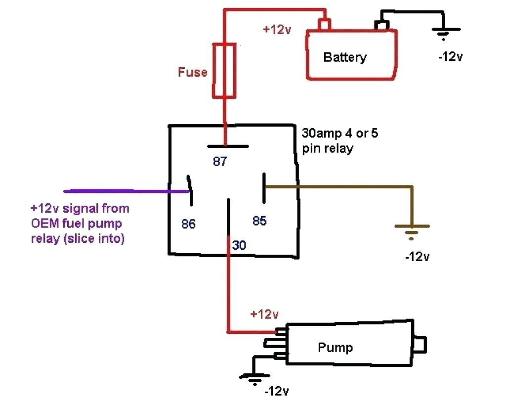
Relay Wiring Diagram 5 Pole. Web wiring diagram images detail: End 87a is used for circuits when power is required when the.
Dorman 5 Pin Relay Wiring Diagram from wiringall.com
4 pin relay wiring diagram vs 5. Next, check the voltage in the wires using a multimeter or test light. Web automotive f relay 40a spst mgi sdware.
Pin's 1 & 4 As Normally Closed.
4 pin relay wiring diagram vs 5. The armature is attracted to the pole of an electromagnet in this type of relay (coil). Next, check the voltage in the wires using a multimeter or test light.
Web The Relay Depicted Above Is An Electromagnetic Attraction Type.
Operations of 5 pin relay. An spdt relay internal configuration has one control input terminal that. Web 1) position the multimeter in the ohms range, preferably in the 1k range.
Web So When Wiring Up These Relays, The Coil Wire's Will Connect To Pins 2 & 7 On The Socket.
I’ve created an actual circuit for you to follow along with, and i explain how they w. Web web pin no 1: A relay can be used to boost current, turn something on/off, or reverse.
The Amount Of Value Given In.
End 87a is used for circuits when power is required when the. Pin's 1 & 3 as normally open. Two pins for the coil.
Not That His Relay Can Be 5 Volts Dcv, 12 Volts Dcv, 24 Volts Dcv, Etc According.
Web automotive f relay 40a spst mgi sdware. Spst refers to single pole single throw relay. 12 volt dc solid state relay using buz71a.