Rm7895A1014 Wiring Diagram. This manual is also suitable for: 1 2 3 4 2 rm7895a1014.
Earth ground terminal that must be grounded to for the ec7895 or rm7895, the maximum length the metal control panel with wire as short as of leadwire. See flame detection specifications for correct wiring. Recommended wire routing of leadwires:
See Flame Detection Specifications For Correct Wiring.
Do not run high voltage. Web flame safeguard conversion wiring diagrams: Clip jumper jr2 if using 3 second flame response time.
Selectable Relight Or Lockout On Loss.
Recommended wire routing of leadwires: Web valve proving system—simplified diagram. High x 5 1/4 in.
Wiring Must Comply With All.
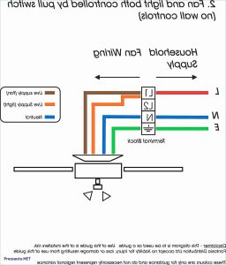
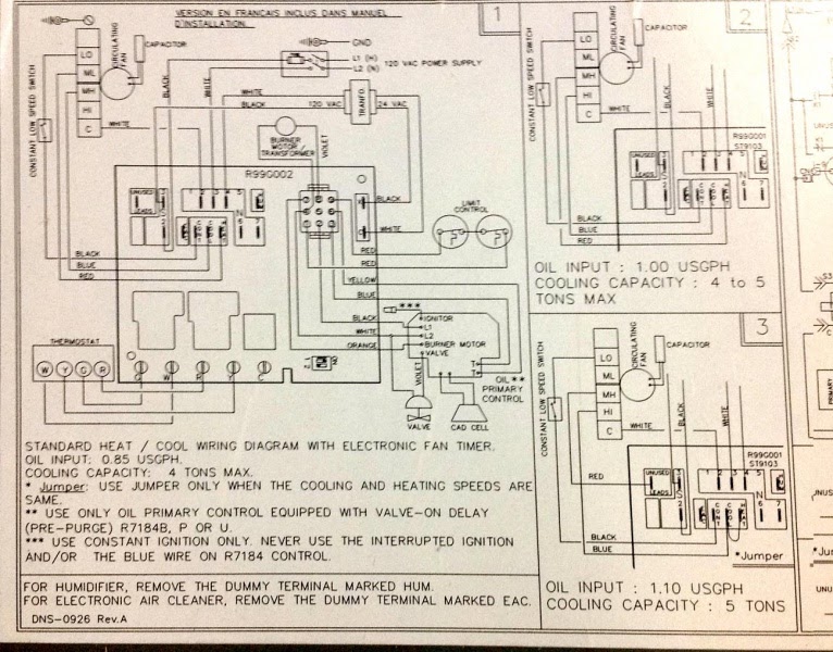
2 and 3 or t he appropriate specifications for proper subbase wiring. Manuals and user guides for honeywell rm7895a1014. Web 12 l2 13 line voltage alarm 3 burner motor (blower) 4 5 burner 6limitscontroller 7air flow switchintermittent pilot ignition 8 5main fuel valve 9 ignition 10 flame detector f3.
Internal Block Diagram Of Rm7897A,C (See Fig.
View online or download honeywell rm7897a1002 installation instructions manual It is located at the most upstream position of the main gas valve train. Wiring connections for the relay modules are unique;
1 2 3 4 2 Rm7895A1014.
Web nonvolatile memory retains history files and sequencing status after power loss. Installation instructions manual | brand: Web the internal block diagram of the rm7895a,b,c,d/ec7895a,c;rm7896a,b,c,d is shown in fig.