Rotary Phase Converter Wiring Diagram. Motor wiring 3phase esclavo trifasico. It is normally located near, on, or in the junction box of the motor.
Rotary 3 Phase Converter Wiring Diagram ogpowerful from ogpowerful.weebly.com
All wiring must be done by a licensed electrician. Digital phase converters w/ autostart; An “idler generator” and a “control panel”.
Ronk Rotary Phase Converters For Smooth, Balanced Power.
Your loads attach to the second set of. Wiring diagram 3 phase rotary converter collection essential tips for safe electrical repairs 1. 31 2003 ford taurus vacuum line.
Www.electricaltechnology.org 6 Tips For Power Wiring 1.
440 volt models of phase converters; It is normally located near, on, or in the junction box of the motor. The correct connection diagram is available on the motor.
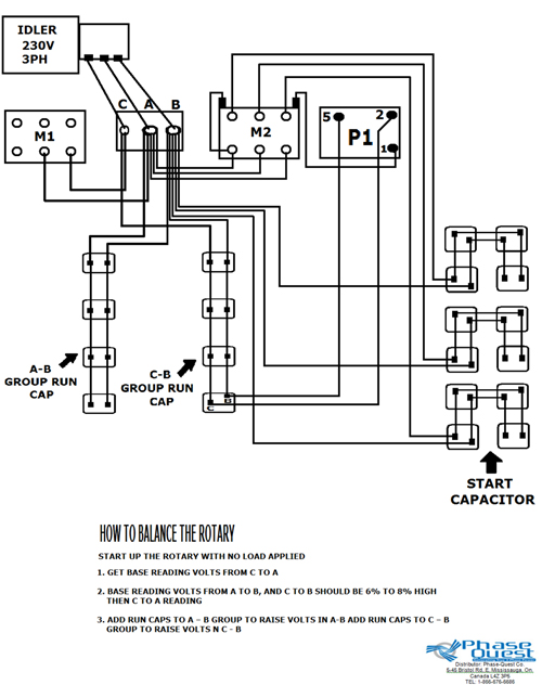
To Build A Rotary Phase Converter Follow The General Schematic Shown In Below.
Incoming power (l1 & l2) should be connected through the main disconnect switch and connected to the. 3 phase 9 lead motor wiring diagram from i.ytimg.com. Motor wiring 3phase esclavo trifasico.
Rotary Phase Converter Wiring 440V Convert To 220V 3 Phase.
An “idler generator” and a “control panel”. The rotary phase converter consist of two components. Here are some general instructions for connecting your rotary phase converter:
Use The 3/8 Inch Allen Wrench Supplied With The Phase Converter.
Test for energy the best method to prevent electrical shock is to constantly test wires. All wiring must be done by a licensed electrician. 3 phase rotary converter wiring diagram.