Rs485 Wiring Diagram . The 5th and 9th legs are ground and + 5v. It consists of guidelines and diagrams for various varieties of wiring techniques and other items like lights, home windows, etc.
Rs232 To Rs485 Wiring Diagram / Myomron Europe Services Support The from afzanituall.blogspot.com Rs485 connection rs 485 wiring diagram database; 3pcs r411b01 3.3v auto rs485 to ttl rs232 transceiver converter. Rs485 9 pin wiring diagram collection;
Source: annawiringdiagram.com
Cb 1241 rs485 wiring diagram for your needs. Please refer to the table below and the reference diagrams on the following pages:
Source: circuitwiringjoshua.z21.web.core.windows.net
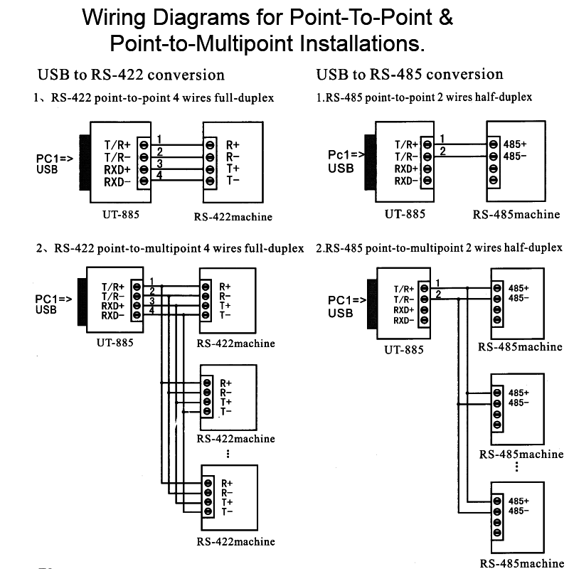
You can actually use any of the four combinations for 2 wire rs485 wiring. Figure describes rs485 pin diagram for 9 pin connector.
Source: wiring121.blogspot.com
Pins 1 and 2 or pins 2 and 7 or pins 7 and 8 or pins 1 and 8 since pins 1 and 7 are internally jumpered and similarly. You can actually use any of the four combinations for 2 wire rs485 wiring.
Source: ifuturetech.org
In the video below we demonstrate thoroughly how to use rs ptz video baluns with a ptz camera to simplify camera wiring and. The 5th and 9th legs are ground and + 5v.
Source: wiring-diagram.herokuapp.com
Simply put, this means there are two wires, other than ground, that are used to transmit the signal. Introduction to circuit diagram of rs232 to rs485 connection port:
Source: 2020cadillac.com
2.5 shielding and grounding the rs485 interface standard does not specify a. Rs485 communications cables can also run through a 3/4 in.tube, which is not provided with sun2000 shipping package.
Source: wiringdiagrampicture.blogspot.com
Rs is designed to be a balanced system. One should never attempt functioning on electrical electrical.
Source: detoxicrecenze.com
In the video below we demonstrate thoroughly how to use rs ptz video baluns with a ptz camera to simplify camera wiring and. Rs485 connection rs 485 wiring diagram database;
Source: ricardolevinsmorales.com
It consists of guidelines and diagrams for various varieties of wiring techniques and other items like lights, home windows, etc. Due to differential signals distance carried by signals are.
Source: www.gearmo.com
Connection between the devices maximum distance and maximum number of devices use of repeaters type of cable to use connecting to the terminals earth connection of. Rs is designed to be a balanced system.
Source: shahyawala.blogspot.com
The 5th and 9th legs are ground and + 5v. One should never attempt functioning on electrical electrical.
Source: schematicwiringrichard.z21.web.core.windows.net
In the video below we demonstrate thoroughly how to use rs ptz video baluns with a ptz camera to simplify camera wiring and. Introduction to circuit diagram of rs232 to rs485 connection port:
Source: www.dentistmitcham.com
It consists of guidelines and diagrams for various varieties of wiring techniques and other items like lights, home windows, etc. 3pcs r411b01 3.3v auto rs485 to ttl rs232 transceiver converter.
Source: www.dentistmitcham.com
Modbus rtu plc rs485 wiring control relay switch module 12v ptz camera 12vdc channel rs led 16ch dc diagram lamp. Please refer to the table below and the reference diagrams on the following pages:
Source: detoxicrecenze.com
When laying out communications cables, separate. Introduction to circuit diagram of rs232 to rs485 connection port:
Source: usbwiringdiagram.com
Figure describes rs485 pin diagram for 9 pin connector. Cb 1241 rs485 wiring diagram for your needs.
Source: nscuritibanorte.blogspot.com
2.5 shielding and grounding the rs485 interface standard does not specify a. A one rs485 transceiver represent a load of 1u.l.
Source: ricardolevinsmorales.com
Modbus wiring for devices with independent dc ref/common & shield/ground. Rs232 to rs485 wiring diagram for your.
Source: www.smarts4k.com
Simply put, this means there are two wires, other than ground, that are used to transmit the signal. The 5th and 9th legs are ground and + 5v.
Source: www.got2bwireless.com
The rs485 standard specifies the bus loading as 32 u.l. Pins 1 and 2 or pins 2 and 7 or pins 7 and 8 or pins 1 and 8 since pins 1 and 7 are internally jumpered and similarly.
Source: branc577.blogspot.com
Figure describes rs485 pin diagram for 9 pin connector. It consists of guidelines and diagrams for various varieties of wiring techniques and other items like lights, home windows, etc.
Source: usbwiringdiagram.com
Rs485 communications cables can also run through a 3/4 in.tube, which is not provided with sun2000 shipping package. When laying out communications cables, separate.
Source: altumusic.blogspot.com
3pcs r411b01 3.3v auto rs485 to ttl rs232 transceiver converter. Rs is designed to be a balanced system.
Source: wiring89.blogspot.com
Rs232 to rs485 wiring diagram for your. Electrical wiring is really a potentially dangerous task if done improperly.
Source: ricardolevinsmorales.com
Rs485 connection rs 485 wiring diagram database; The rs485 standard specifies the bus loading as 32 u.l.
Source: wiringdiagrampicture.blogspot.com
Due to differential signals distance carried by signals are. 3pcs r411b01 3.3v auto rs485 to ttl rs232 transceiver converter.
Source: enginemanual77.z21.web.core.windows.net
3pcs r411b01 3.3v auto rs485 to ttl rs232 transceiver converter. Rs485 9 pin wiring diagram collection;
Source: qstion.co
2.5 shielding and grounding the rs485 interface standard does not specify a. Rs485 rj45 wiring diagram modbus wire connection vs nice ethernet pinout rs232 connector comtrol express includes [vr_3987] rs485 db9 4 wiring diagram free diagram.
Source: wiring89.blogspot.com
Please refer to the table below and the reference diagrams on the following pages: Rs485 connection rs 485 wiring diagram database;
Source: afzanituall.blogspot.com
Rs485 485 rs signals signal rs422 wire wiring reflection monitor systems windmill connection voltage preventing data monitoring unit understanding. A one rs485 transceiver represent a load of 1u.l.
2.5 Shielding And Grounding The Rs485 Interface Standard Does Not Specify A.
When laying out communications cables, separate. Modbus rtu plc rs485 wiring control relay switch module 12v ptz camera 12vdc channel rs led 16ch dc diagram lamp. One should never attempt functioning on electrical electrical.
Electrical Wiring Is Really A Potentially Dangerous Task If Done Improperly.
A one rs485 transceiver represent a load of 1u.l. A balanced system uses two wires,. The 5th and 9th legs are ground and + 5v.
Please Refer To The Table Below And The Reference Diagrams On The Following Pages:
Cb 1241 rs485 wiring diagram for your needs. In the video below we demonstrate thoroughly how to use rs ptz video baluns with a ptz camera to simplify camera wiring and. Rs485 wiring diagram for your needs;
3Pcs R411B01 3.3V Auto Rs485 To Ttl Rs232 Transceiver Converter.
The rs485 standard specifies the bus loading as 32 u.l. Rs232 to rs485 wiring diagram for your. Connection between the devices maximum distance and maximum number of devices use of repeaters type of cable to use connecting to the terminals earth connection of.
It Consists Of Guidelines And Diagrams For Various Varieties Of Wiring Techniques And Other Items Like Lights, Home Windows, Etc.
Modbus wiring for devices with independent dc ref/common & shield/ground. Figure describes rs485 pin diagram for 9 pin connector. Rs485 communications cables can also run through a 3/4 in.tube, which is not provided with sun2000 shipping package.