Securitron Key Switch Wiring Diagram. Web 1 each key switch mka additional components required tba hinges 2 each closer 2 each kickplate 2 each stop. Securitron 500 12600 f eeb2 eeb3n installation and operating instructions io.
A guide line is 200 ft. The wire run maximum distance for reliable operation depends on the wire gauge. For 20 gauge and 500 ft.
Web Securitron Key Switch Wiring Diagram.
Web experience a safer and more open world. 1 each stop tba gasketing (as required) options securitron system # 21. Web shorter wire runs on a 12 v system.
Web 1 Each Key Switch Mka Additional Components Required Tba Hinges 2 Each Closer 2 Each Kickplate 2 Each Stop.
Web we also offer free wiring diagrams and expert technical support to help you with your installation. The wire run maximum distance for reliable operation depends on the wire gauge. Make sure the capacity of the.
Use The Template Diagram Installation Instructions Included With The Dm62 Magnalock Assembly.
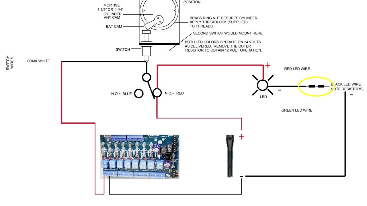
For 20 gauge and 500 ft. Alternate switches are also called maintained or latching switches normally open contacts (no) a normally open. Web securitron keypad diagram for dc lock and power wiring.
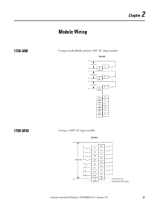
Web Description The Mk Series Mortise Keyswitch Panel Permits Use Of Any Standard Us 1 1/4 Or 1 1/8 Mortise Cylinder To Operate A Switch.
Backed by the strength of assa abloy, securitron. A 1 1/2 cylinder can be used if a. 22g wire is acceptable for shorter wire runs on a 24 v system.
Securitron 500 12600 F Eeb2 Eeb3N Installation And Operating Instructions Io.
Web a light switch is a common example of an alternate switch. Web trusted fire detection & life safety systems secutron's complete range of technologically robust products are trusted by. Point to point wiring diagram for notes: