Shifnoid Wiring Diagram. Shifter handle new spacer release handle new lock nut existing washer new spacer new. Web c shifnoid ltd., 2014 from normally open ground on your rpm switch or timer if your rpm switch or timer supplies normally open ground (shifnoid or msd) use this diagram 87.
Web c shifnoid ltd., 2010 from normally open ground on your rpm switch or timer if your rpm switch or timer supplies normally open ground (shifnoid or msd) use this diagram 87. Web shifnoid wiring diagram shifnoid ncrpm3000 rpm switch with delay to transbrake switch or transbrake solenoid blue terminal on delay box red to +12v rpm module + rpm switch to. Web electric shifter wiring to msd 8950
Ss2Rpm Solenoid Shifter & Rpm Switch.
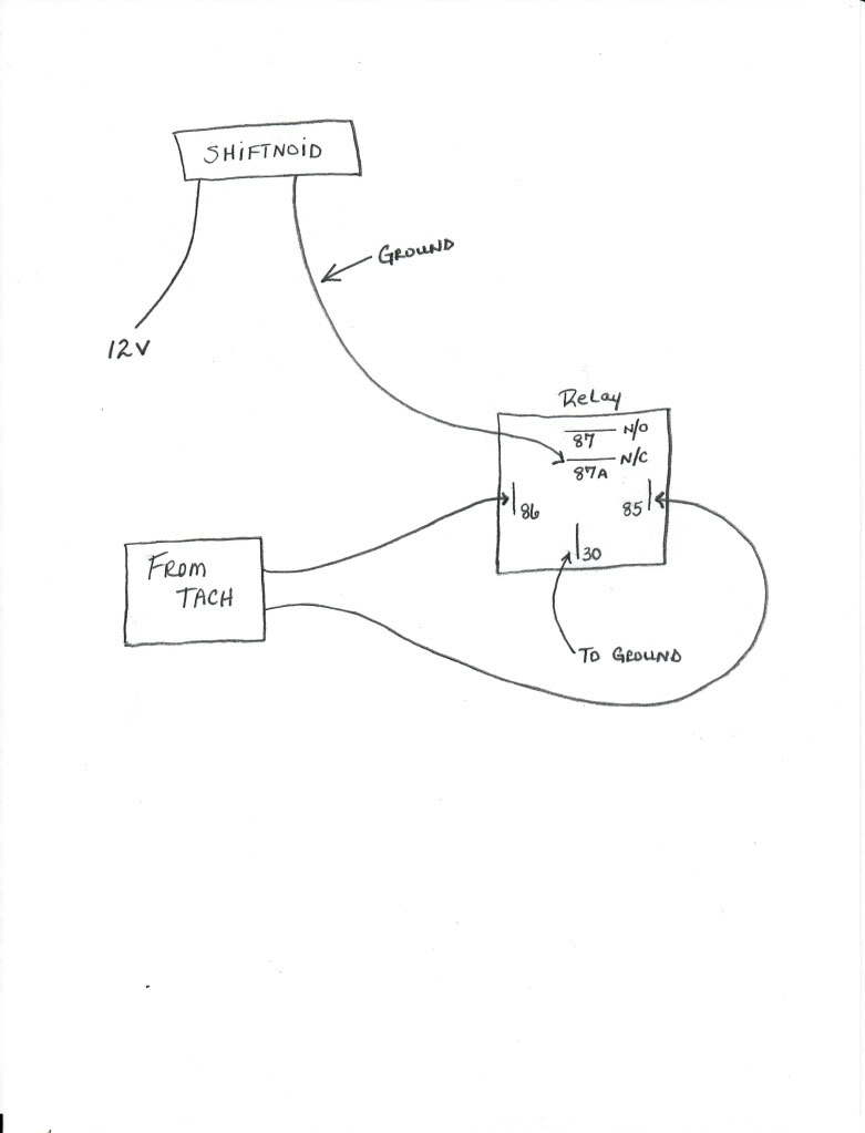
Click on any of these wiring diagrams included in smartdraw and edit them:. To wire the relay to your. If your rpm switch or timer supplies normally open ground” connect the trigger wire from your device to post 86 on.
Web Shifnoid Wiring Diagram Shifnoid Ncrpm3000 Rpm Switch With Delay C Shifnoid Ltd., 2011 + + + + Shifnoid Rpmswitch W/Delay R +12V +12V +12V.
If your rpm switch or timer supplies “normally open. The yellow wire is normally open and will activate a circuit by switching to ground. Web stop at this point to wire the switches that go under the aluminum cover.
Web 12 Gauge Wire 12 Gauge Wire 12 Gauge Wire 12 Gauge Wire From Normally Open +12V On Your Rpm Switch Or Timer If Your Rpm Switch Or Timer Supplies Normally Open +12V”.
Web c shifnoid ltd., 2010 from normally open ground on your rpm switch or timer if your rpm switch or timer supplies normally open ground (shifnoid or msd) use this diagram 87. Connect post 30 to either solenoid wire. 87 * +12v to switched side of main battery disconnect switch 85 * shifnoid interface relay(leads to n.c.
Msd 7Al 3 Ignition Control 7230 Kit Installation Instructions 121 Rpm Activated Switch 7330 User.
Web shifnoid wiring diagram for a hurst quarter stick with a sn5055h three speed solenoid kit. If your rpm switch or timer supplies normally open ground” connect the trigger wire from your device to post 86 on. Web wiring diagrams 1) when using an msd rpm activator switch follow this diagram black red 12 volts activated yellow rpm module tach output black for.
Web The Best Way To Understand Wiring Diagrams Is To Look At Some Examples Of Wiring Diagrams.
Shifter handle new spacer release handle new lock nut existing washer new spacer new. Web shifnoid wiring diagram shifnoid ncrpm3000 rpm switch with delay to transbrake switch or transbrake solenoid blue terminal on delay box red to +12v rpm module + rpm switch to. Remove the original b&m neutral safety switch and replace it with the shifnoid safety switch.