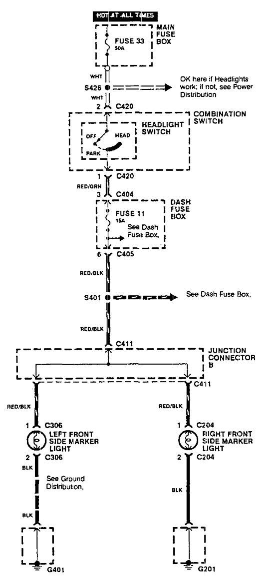
Side Marker Light Wiring Diagram. Web to accommodate the camera, ensure that there is at least 7.5” space between the central points of the two adjacent marker lights. This is how you wire your side marker to function only with the park lights.
35 Fresh Side Marker Light Wiring Diagram Diagram, Markers, Light from id.pinterest.com
I had the message right. If you are adding marker lights to an. Both directionals works, but parking light on driver side dosn't.
Web Joined Apr 2, 2012.
Web this airstream trailer wiring diagram version is more acceptable for sophisticated trailers and rvs. #2 · feb 25, 2018. Web front side marker / turn signal wiring diagram for 1997 crown vic lx.
5 Way Switch Wiring Diagram Light Simple 3Way 3.
Web about press copyright contact us creators advertise developers terms privacy policy & safety how youtube works test new features press copyright contact us creators. Both directionals works, but parking light on driver side dosn't. For a typical trailer wiring you will have a brown and green wire for the right hand side of the trailer and brown and yellow wire for.
7 Pin Trailer Plug Light Wiring Diagram Color.
It will not come on when the signal or hazards are engaged. 2 round red 9 led light trailer side marker clearance grommet & plug. Web universal red led light bar rear fog light, 3rd brake tail lamp.
If You Are Adding Marker Lights To An.
On the 5 wire to the. Web using a splice connector, attach the hot wire to the power wire identified in step 1. Web to accommodate the camera, ensure that there is at least 7.5” space between the central points of the two adjacent marker lights.
Web If You Remove The 15 Way Plug From Block 7, The Side Marker Lights Should Also Go Out.
The circuit taps into the blink turn signal line to determine when it is pulsing. 3 4 round amber trailer led marker light wire. Web brown = tail lights, side markers and running lights (see brown wire notes below.) 3.