Timer Delay Relay Wiring Diagram. Web tdr (time delay relay) sering disebut juga relay timer atau relay penunda batas waktu banyak digunakan dalam instalasi motor terutama instalasi yang membutuhkan. On/off switch) +24v (from fused battery feed) earth wiring.
Timer relays are a basic and essential part of any modern electrical circuit. Use cu wire of 75 dec. 2,205 views apr 27, 2021 on delay timer wiring diagram | 8 pin timer relay wiring diagram.
Timer Relays Are A Basic And Essential Part Of Any Modern Electrical Circuit.
Web 8 pin timer relay wiring diagram jr electric school 262k subscribers subscribe 961 84k views 1 year ago electrical diagram video a timer relay is a. 2,205 views apr 27, 2021 on delay timer wiring diagram | 8 pin timer relay wiring diagram. Web memahami tdr timer delay relay atau saklar waktu.
They Are Represented By The Dotted Lines.
Use cu wire of 75 dec. Web on delay timer wiring diagram | 8 pin timer relay wiring diagram | mian electric. Web the following is a timing diagram of this relay contact’s operation:
Web Guide To Wiring Diagrams For Timer Relays.
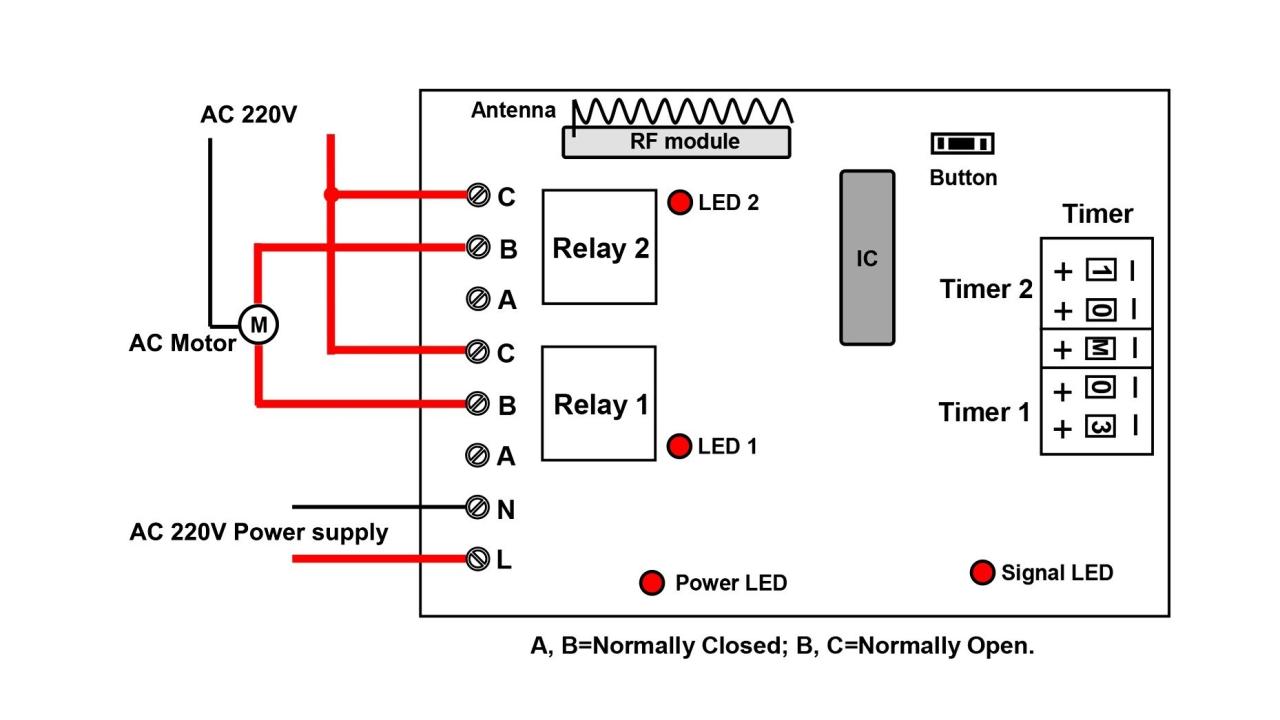
They are used to control the timing of. Semoga aktifitas kita semua selalu ada dalam jalan yang benar. Web the wiring diagram below shows how the relay should be connected.
Pada Kesempatan Kali Ini Saya Akan Membahas Mengenai.
On/off switch) +24v (from fused battery feed) earth wiring. Terminals 15 and 31 are for the timer circuit, terminals 30, 87 & 87a are for the main power circuit terminal 30. Every time delay relay has an internal relay (usually mechanical) with contacts that open & close to control the load.
Web Tdr (Time Delay Relay) Sering Disebut Juga Relay Timer Atau Relay Penunda Batas Waktu Banyak Digunakan Dalam Instalasi Motor Terutama Instalasi Yang Membutuhkan.
Set the time delay period t1 on each timer. Web delay on break timer wiring diagram. Web however, these methods are cost ineffective.three circuits are explained here are 1)simple adjustable timer using 555 ic,2)a cyclic on/off timer using 555.