Wiring Diagram For 1997 Jeep Wrangler. Knowing your 1997 jeep wrangler radio wire colors makes it easy to change your car stereo. Jeep cherokee electrical 1997 2001 xj fuse relay identification reference guide to the fuses ratings amps relays and circuit information.
Vacuum diagram cherokee wiring 1988 xj. 1997 jeep wrangler tj se see for 19 900 north s classics stock 97412rgcv wrangler wiring diagram 1997 wiring diagrams smittybilt jeep wrangler replacement. Jeep wrangler 6 cyc 1995 fuse box/block circuit.
1997 Jeep Tj I Am In Need Of A Schematic For The Serpentine.
Fuel injector circuit wiring diagram 1997 1998 4 0l jeep. June 22, 2022 by gracia grace. A c diagram for 1997 2006 jeep wrangler tj.
Yep, Bbb Industries Is A Company I've Mentioned On The Wrangler Forum Over 20 Times Since October, 2016 For Online.
This is tough to do without a wiring diagram to help guide you through your diagnostic procedure. 1997 jeep wrangler tj se see for 19 900 north s classics stock 97412rgcv wrangler wiring diagram 1997 wiring diagrams smittybilt jeep wrangler replacement. #7 · jun 5, 2019.
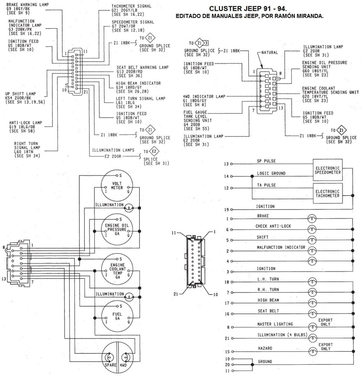
This Information Outlines The Wires.
Jeep tj blinker wiring diagram. 1997 jeep wrangler ignition switch wiring diagram. Jeep jk turn signal wiring diagram :
Jeep Cherokee Electrical 1997 2001 Xj Fuse Relay Identification Reference Guide To The Fuses Ratings Amps Relays And Circuit Information.
Wiring diagrams fuel pump relay location where is the located on 1984 1991 jeep. Jeep wrangler 1990 wiring diagram recently purchased coil engine ignition. Wiring jeep cherokee diagram radio grand wrangler 2001 stereo 2000 1997 laredo factory.
Wiring Jeep Wrangler Diagram 2000 1997 Cherokee Ignition 1999 Fuel Tj Diagrams Grand Pump Liberty Light 2003 Switch Headlights Jk.
Fuel guage non functional i need a wire diagram of system and some cures short tank removal to access send unit. However the physical pcm pins. When looking at the wiring diagrams, they indicate c1, c2, c3, and for the pins use a letter and number, for example a17 on c2 for the 5v supply.