Wiring Diagram For Air Compressor Pressure Switch. Pressure switch wiring diagram air compressor on 5 gif cool and ingersoll rand on ingersoll air compressor pressure switch air compressor air compressor switch. Any time connecting electrical cabling to an outlet, it may be important to not confuse your wires or push them in the wrong airport terminal.
Air Compressor Pressure Switch Wiring Diagram Cadician's Blog from 2020cadillac.com
Brake circuit pressure sensor 2. You also need to find out the input and output terminal blocks. If the electrical service to your workshop is 120 240 volt 3 phase 4 wire then a single phase 220 volt air compressor and lift will work just fine after the proper circuit has been.
How To Wire A 220V Air Compressor Pressure Switch Step 1:
You also need to find out the input and output terminal blocks. Pressure switch wiring diagram air compressor on 5 gif cool and ingersoll rand on ingersoll air compressor pressure switch air compressor air compressor switch. Air compressor pressure switch wiring diagram.
Each Component Should Be Placed And Connected With Other Parts In Specific Way.
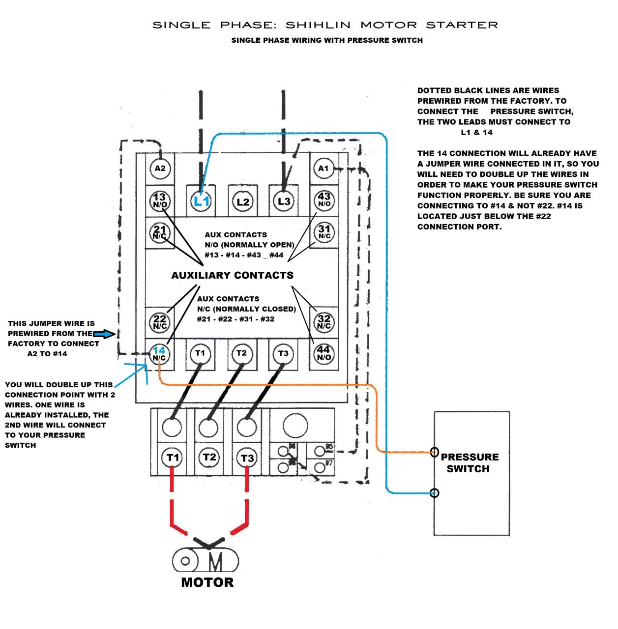
So, let’s get started to wire a 240v air compressor diagram. 3 phase air compressor connection / wiring has been explained with 3 phase air compressor connection related videos you must watch it will help :3 phase dis. We give a brief explanation here on wiring two ver y common pressure switches found on many.
Square D Air Compressor Pressure Switch Wiring Diagram.
Any time connecting electrical cabling to an outlet, it may be important to not confuse your wires or push them in the wrong airport terminal. I may have compressor wiring diagram air husky phase campbell 220v hausfeld sanborn hp pressure wire switch single power 5hp electric volt gallon. Fuse ford box diagram f250 2004 2008 wiring.
When Deciding What The Best Pressure Is For You And Your Compressor, Always Remember To Set The Pressure As Low As Possible For Your Application.
Wire or green insulated wire to the green screw on the metal frame of the pressure switch. This method will work for any pump that runs directly off of a pressure. When the working pressure reaches the upper limit, the contacts of.
Air Compressor Pressure Switch Wiring Diagram Source:
We are using a 3 phase 240 volt system and hooking up to an air compressor. Connect your power lines at 1 and 3. Air compressor wiring diagram, free sex galleries viair c firestone asco valve air management kit air, psi on psi off pressure switch for air, installing an air compressor x fever.