Wiring In A Switch Diagram. These are the white wire, the black wire, the red wire, and the green wire. Our dimmer switches are 2 way, ie can be used for switching lights from either one or two places, but the other switch needs to be a standard rocker, dolly or on/off dummy dimmer switch.
Video on how to wire a three way switch from www.askmediy.com
Two way switch wiring one gang and multiway. A wiring diagram is a schematic which uses abstract pictorial symbols to exhibit each of the interconnections of. A float switch is a type of level sensor, a device used to detect the level of liquid within a tank.
Most Home Lighting Circuits Are 15 Amp, Which Only Requires 14 Gauge Wire.
How to install a double pole switch wire 3 way light diy wiring diagram for 2 single. Explanation of wiring diagram #1 switch wiring shows the power source (power in) starts at the switch box. Splice the ends of the green wire (ground) together with the other end of the pigtail.
These Wiring Diagrams Help You.
Wire battery (to function as the power source) bulb. A float switch is a type of level sensor, a device used to detect the level of liquid within a tank. 3 way switch wiring diagram part 1 3way switch wiring diagrams #1, #2 and #3 the key to three way switch wiring depends on two main factors.
The Above Light Switch Wiring Diagram Depicts The Power From The Circuit Breaker Panel Going To An Electrical Receptacle Outlet, Then Continuing To The Next Outlet, Then To A Single Pole Wall Switch,.
A wiring diagram is a schematic which uses abstract pictorial symbols to exhibit each of the interconnections of. Two way switch wiring one gang and multiway. Light switch wiring diagrams do it yourself help com.
In Order To Commence The Process Of Wiring A Micro Switch Based On The Diagram, Some Items Will Be Required.
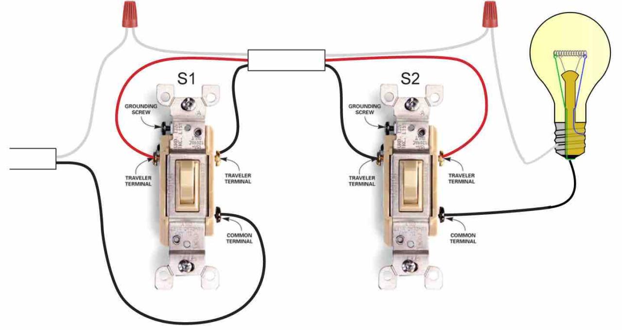
Today i showed you with wiring diagram for water pump operated by float switch. Our dimmer switches are 2 way, ie can be used for switching lights from either one or two places, but the other switch needs to be a standard rocker, dolly or on/off dummy dimmer switch. The black wire is going to be connected to the black screw on the switch the main wire that will go from one switch to the other should have 4 wires total (black, white, ground and red).
The Diagram Here Shows (2) Outlets Wired In Series And More Outlets Can Be Added To This Circuit By Wiring The 2Nd Outlet Just Like The 1St Outlet To Keep The Circuit Continuing On Until You End.
Follow the switch manufacturer’s instructions and wiring diagram as the connections on the switch vary by. If you are going to install a new one then go. This wiring diagram shows both switches aligned together with the fixture at the end.